ENGLISH
Protector circuit
•This unit is equipped with a
In such a case, the protection circuit will operate to cut off the output to the speakers. Should this happen, turn the power off and check the speaker connections. Then turn the power on again. After muting for several seconds, the receiver should be operating normally.
If the protection circuit is activated again even though there are no problems with the wiring or the ventilation around the unit, switch off the power and contact a DENON service center.
Note on speaker impedance
•The protector circuit may be activated if the set is played for long periods of time at high volumes when speakers with an impedance lower than the specified impedance (for example speakers with an impedance of lower than 4 Ω/ohms) are connected. If the protector circuit is activated, the speaker output is cut off. Turn off the set’s power, wait for the set to cool down, improve the ventilation around the set, then turn the power back on.
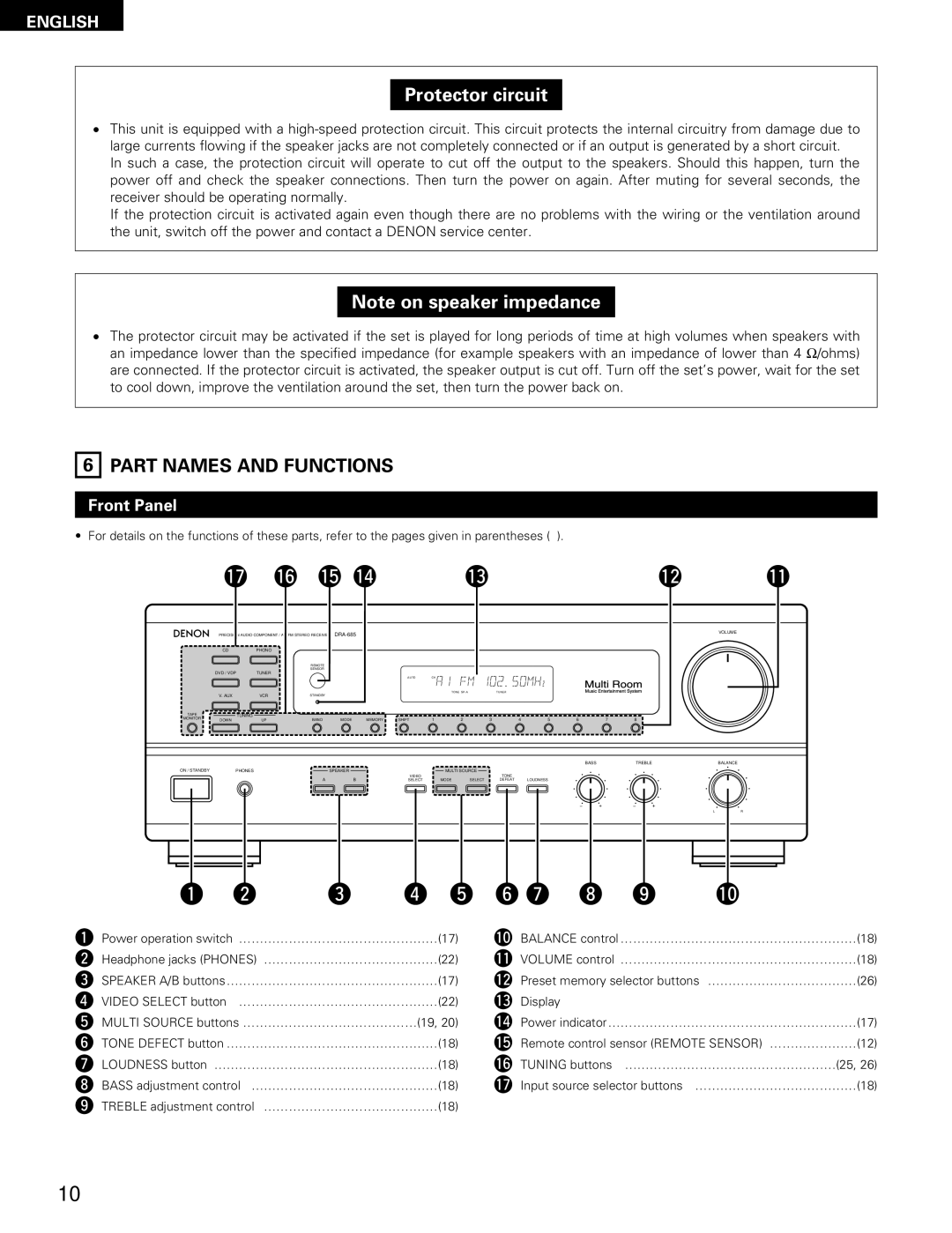
6 PART NAMES AND FUNCTIONS
Front Panel
• For details on the functions of these parts, refer to the pages given in parentheses ( ).
| !7 |
| !6 !5 !4 |
|
| !3 |
|
|
|
| !2 | !1 | |||
B PRECISION AUDIO COMPONENT / |
|
|
|
|
|
|
|
|
|
| VOLUME | ||||
|
|
|
|
|
|
|
|
|
|
| |||||
| CD | PHONO |
|
|
|
|
|
|
|
|
|
|
|
|
|
|
|
| REMOTE |
|
|
|
|
|
|
|
|
|
|
|
|
|
|
| SENSOR |
|
|
|
|
|
|
|
|
|
|
|
|
| DVD / VDP | TUNER |
|
|
|
|
|
|
|
|
|
|
|
|
|
|
|
|
|
|
| AUTO | CH |
|
|
|
|
|
|
|
|
| V. AUX | VCR | STANDBY |
|
|
| TONE | TUNER |
|
|
|
|
|
| |
|
|
|
|
|
|
|
|
|
|
|
|
| |||
TAPE | TUNING |
|
|
|
|
|
|
|
|
|
|
|
|
|
|
MONITOR | DOWN | UP | BAND | MODE | MEMORY | SHIFT | 1 | 2 | 3 | 4 | 5 | 6 | 7 | 8 |
|
|
|
|
|
|
|
|
|
|
|
|
|
| BASS | TREBLE | BALANCE |
ON / STANDBY | PHONES |
| SPEAKER |
|
| MULTI SOURCE |
|
|
|
|
|
|
| ||
|
|
| A | B |
| VIDEO |
|
| TONE |
|
|
|
|
|
|
|
|
|
| SELECT | MODE | SELECT | DEFEAT |
| LOUDNESS |
|
|
|
| ||
|
|
|
|
|
|
|
|
|
|
|
|
|
| L | R |
q w | e r t y u i o !0 |
qPower operation switch …………………………………………(17)
wHeadphone jacks (PHONES) ……………………………………(22)
eSPEAKER A/B buttons ……………………………………………(17)
r VIDEO SELECT button …………………………………………(22)
tMULTI SOURCE buttons ……………………………………(19, 20)
yTONE DEFECT button ……………………………………………(18)
uLOUDNESS button ………………………………………………(18)
iBASS adjustment control ………………………………………(18)
o TREBLE adjustment control ……………………………………(18)
!0BALANCE control …………………………………………………(18)
!1VOLUME control …………………………………………………(18)
!2Preset memory selector buttons ………………………………(26)
!3Display
!4Power indicator ……………………………………………………(17)
!5Remote control sensor (REMOTE SENSOR) …………………(12)
!6TUNING buttons ……………………………………………(25, 26)
!7Input source selector buttons …………………………………(18)
10