10
VENTING INSTALLATION INSTRUCTIONS
Installation Planning (Cont.)
VENTING INSTALLATION INSTRUCTIONS Continued
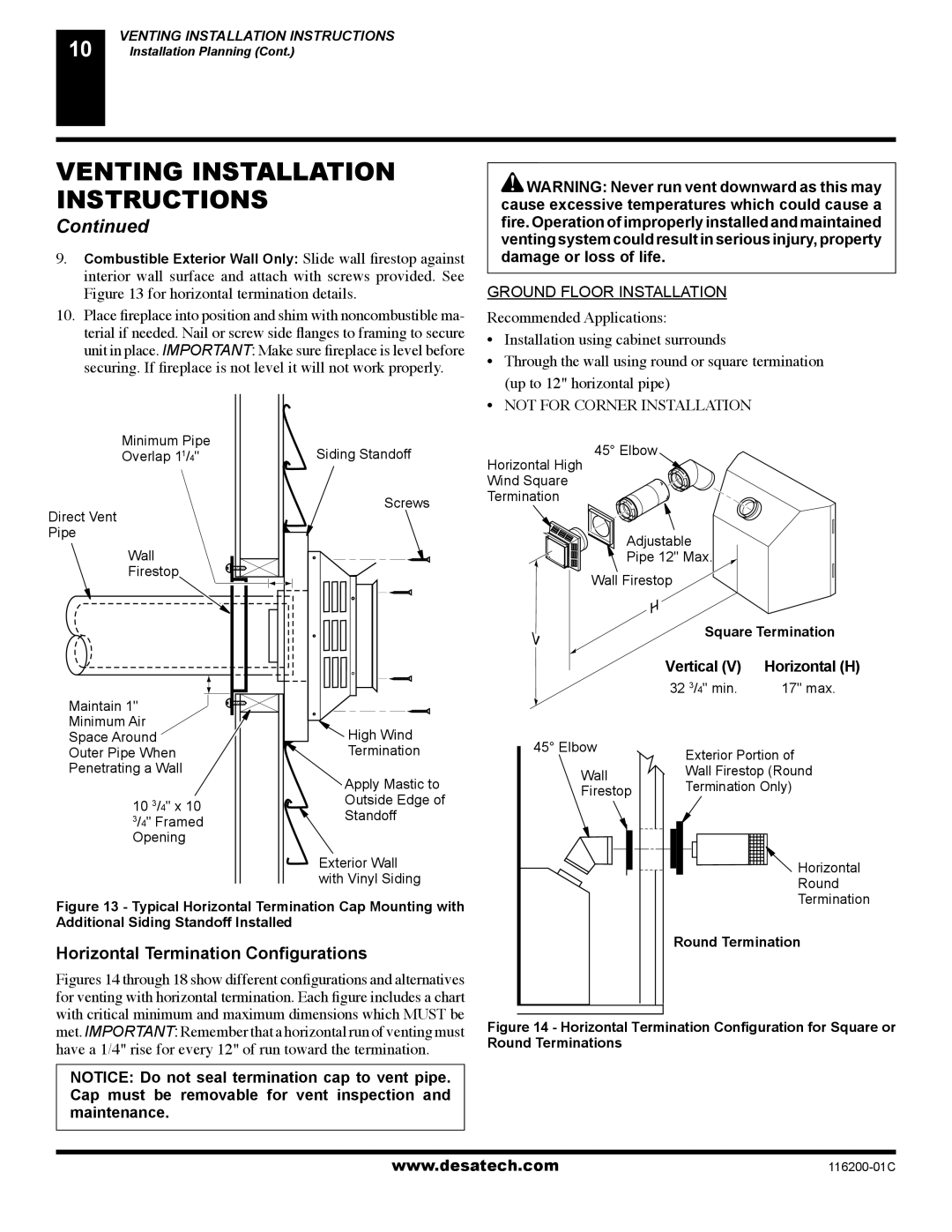
9.Combustible Exterior Wall Only: Slide wall firestop against interior wall surface and attach with screws provided. See Figure 13 for horizontal termination details.
10.Place fireplace into position and shim with noncombustible ma- terial if needed. Nail or screw side flanges to framing to secure unit in place. IMPORTANT: Make sure fireplace is level before securing. If fireplace is not level it will not work properly.
Minimum Pipe | Siding Standoff | |
Overlap 1 | /4" | |
1 |
|
|
Direct Vent |
| Screws |
|
| |
Pipe |
|
|
Wall |
|
|
Firestop |
|
|
Maintain 1" |
|
|
|
| |
Minimum Air |
|
|
| High Wind | |
Space Around |
|
| |||
Outer Pipe When |
| Termination | |||
Penetrating a Wall |
|
| |||
|
|
|
|
| Apply Mastic to |
10 | 3 | /4" x | 10 | Outside Edge of | |
| Standoff | ||||
3 | /4" Framed | ||||
|
| ||||
Opening |
|
| |||
|
|
|
|
| Exterior Wall |
|
|
|
|
| with Vinyl Siding |
Figure 13 - Typical Horizontal Termination Cap Mounting with | |||||
Additional Siding Standoff Installed |
| ||||
Horizontal Termination Configurations
Figures 14 through 18 show different configurations and alternatives for venting with horizontal termination. Each figure includes a chart with critical minimum and maximum dimensions which MUST be met. IMPORTANT: Remember that a horizontal run of venting must have a 1/4" rise for every 12" of run toward the termination.
NOTICE: Do not seal termination cap to vent pipe. Cap must be removable for vent inspection and maintenance.
![]() WARNING: Never run vent downward as this may cause excessive temperatures which could cause a fire. Operation of improperly installed and maintained venting system could result in serious injury, property damage or loss of life.
WARNING: Never run vent downward as this may cause excessive temperatures which could cause a fire. Operation of improperly installed and maintained venting system could result in serious injury, property damage or loss of life.
GROUND FLOOR INSTALLATION
Recommended Applications:
•Installation using cabinet surrounds
•Through the wall using round or square termination (up to 12" horizontal pipe)
•NOT FOR CORNER INSTALLATION
45° Elbow
Horizontal High
Wind Square
Termination
Adjustable |
|
| ||
Pipe 12" Max. |
| |||
Wall Firestop |
|
|
| |
|
| Square Termination | ||
Vertical (V) | Horizontal (H) | |||
32 | 3 | /4" min. | 17" max. | |
45° Elbow | Exterior Portion of | |||
| ||||
Wall | Wall Firestop (Round | |||
Termination Only) | ||||
Firestop | ||||
|
|
| ||
|
|
| Horizontal | |
|
|
| Round | |
|
|
| Termination | |
Round Termination | ||||
Figure 14 - Horizontal Termination Configuration for Square or Round Terminations
www.desatech.com |