OWNER’S MANUAL
SERVICE
PROCEDURES
Continued
NOZZLE ASSEMBLY
1. | Remove upper shell (see page 8). |
2. | Remove fan (see page 13). |
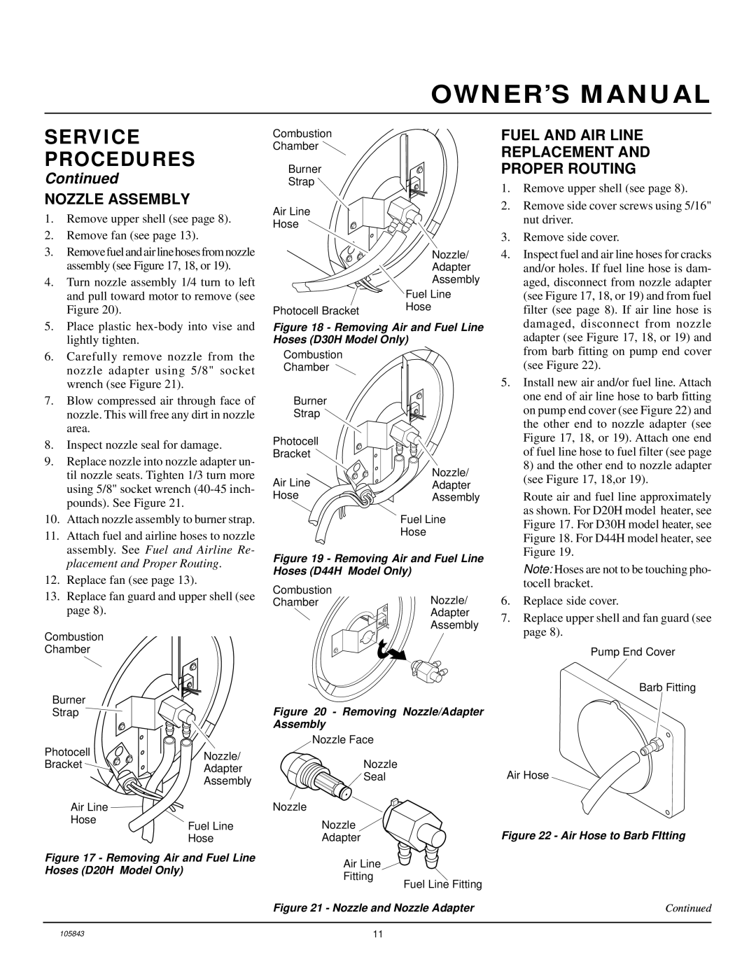
3. | Remove fuel and air line hoses from nozzle |
| assembly (see Figure 17, 18, or 19). |
4. | Turn nozzle assembly 1/4 turn to left |
| and pull toward motor to remove (see |
| Figure 20). |
Combustion Chamber ![]()
Burner
Strap
Air Line
Hose
Photocell Bracket
Nozzle/
Adapter
Assembly
Fuel Line
Hose
FUEL AND AIR LINE
REPLACEMENT AND
PROPER ROUTING
1. | Remove upper shell (see page 8). |
2. | Remove side cover screws using 5/16" |
| nut driver. |
3. | Remove side cover. |
4. | Inspect fuel and air line hoses for cracks |
| and/or holes. If fuel line hose is dam- |
| aged, disconnect from nozzle adapter |
| (see Figure 17, 18, or 19) and from fuel |
| filter (see page 8). If air line hose is |
5. Place plastic |
lightly tighten. |
Figure 18 - Removing Air and Fuel Line Hoses (D30H Model Only)
damaged, disconnect from | nozzle |
adapter (see Figure 17, 18, or 19) and | |
6. | Carefully remove nozzle from the |
| nozzle adapter using 5/8" socket |
| wrench (see Figure 21). |
7. | Blow compressed air through face of |
| nozzle. This will free any dirt in nozzle |
| area. |
8. | Inspect nozzle seal for damage. |
9. | Replace nozzle into nozzle adapter un- |
| til nozzle seats. Tighten 1/3 turn more |
| using 5/8" socket wrench |
| pounds). See Figure 21. |
10. | Attach nozzle assembly to burner strap. |
11. | Attach fuel and airline hoses to nozzle |
| assembly. See Fuel and Airline Re- |
Combustion
Chamber
Burner
Strap ![]()
Photocell
Bracket ![]()
Air Line
Hose
Nozzle/
Adapter
Assembly
Fuel Line
Hose
from barb fitting on pump end cover |
(see Figure 22). |
5. Install new air and/or fuel line. Attach |
one end of air line hose to barb fitting |
on pump end cover (see Figure 22) and |
the other end to nozzle adapter (see |
Figure 17, 18, or 19). Attach one end |
of fuel line hose to fuel filter (see page |
8) and the other end to nozzle adapter |
(see Figure 17, 18,or 19). |
Route air and fuel line approximately as shown. For D20H model heater, see Figure 17. For D30H model heater, see Figure 18. For D44H model heater, see Figure 19.
| placement and Proper Routing. |
12. | Replace fan (see page 13). |
13. | Replace fan guard and upper shell (see |
| page 8). |
Combustion
Chamber
Figure 19 - Removing Air and Fuel Line Hoses (D44H Model Only)
Combustion | Nozzle/ |
Chamber | |
| Adapter |
| Assembly |
Note: Hoses are not to be touching pho- tocell bracket.
6.Replace side cover.
7.Replace upper shell and fan guard (see page 8).
Pump End Cover
Barb Fitting
Burner |
| Figure 20 - Removing Nozzle/Adapter | |
Strap |
| ||
|
| Assembly | |
Photocell |
| Nozzle Face | |
Nozzle/ | Nozzle | ||
Bracket | |||
Adapter | |||
| Seal | ||
| Assembly | ||
|
| ||
Air Line |
| Nozzle | |
Hose | Fuel Line | Nozzle | |
| |||
| Hose | Adapter |
Figure 17 - Removing Air and Fuel Line | Air Line | |
Hoses (D20H Model Only) | ||
Fitting | ||
| ||
| Fuel Line Fitting | |
| Figure 21 - Nozzle and Nozzle Adapter |
Air Hose
Figure 22 - Air Hose to Barb FItting
Continued
105843 | 11 |
