OWNER’S MANUAL
SERVICE
PROCEDURES
Continued
FAN
IMPORTANT: Remove fan from motor shaft before removing motor from heater. The weight of the motor resting on the fan could damage the fan pitch.
1. | Remove upper shell (see page 8). |
2. | Use 1/8" allen wrench to loosen set- |
| screw which holds fan to motor shaft. |
3. | Slip fan off motor shaft. |
4. | Clean fan using a soft cloth moistened |
| with kerosene or solvent. |
5. | Dry fan thoroughly. |
6. | Replace fan on motor shaft. Place fan |
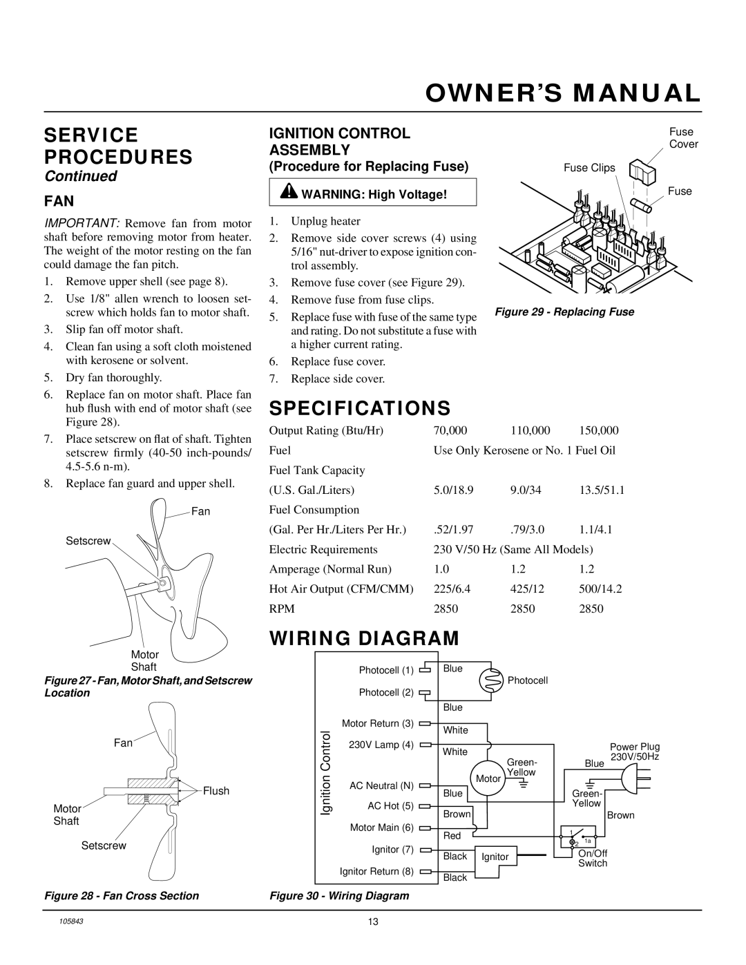
IGNITION CONTROL
ASSEMBLY
(Procedure for Replacing Fuse)
![]() WARNING: High Voltage!
WARNING: High Voltage!
1.Unplug heater
2.Remove side cover screws (4) using 5/16"
3.Remove fuse cover (see Figure 29).
4.Remove fuse from fuse clips.
5.Replace fuse with fuse of the same type and rating. Do not substitute a fuse with a higher current rating.
6.Replace fuse cover.
7.Replace side cover.
Fuse
Cover
Fuse Clips
Fuse
Figure 29 - Replacing Fuse
| hub flush with end of motor shaft (see |
| Figure 28). |
7. | Place setscrew on flat of shaft. Tighten |
| setscrew firmly |
| |
8. | Replace fan guard and upper shell. |
Fan
Setscrew
SPECIFICATIONS
Output Rating (Btu/Hr) | 70,000 | 110,000 | 150,000 |
Fuel | Use Only Kerosene or No. 1 Fuel Oil | ||
Fuel Tank Capacity |
|
|
|
(U.S. Gal./Liters) | 5.0/18.9 | 9.0/34 | 13.5/51.1 |
Fuel Consumption |
|
|
|
(Gal. Per Hr./Liters Per Hr.) | .52/1.97 | .79/3.0 | 1.1/4.1 |
Electric Requirements | 230 V/50 Hz (Same All Models) | ||
Amperage (Normal Run) | 1.0 | 1.2 | 1.2 |
Hot Air Output (CFM/CMM) | 225/6.4 | 425/12 | 500/14.2 |
RPM | 2850 | 2850 | 2850 |
WIRING DIAGRAM
Motor
Shaft
Figure 27 - Fan, Motor Shaft, and Setscrew Location
Fan
![]() Flush
Flush
Motor
Shaft
| Photocell (1) | Blue | |
|
| Photocell | |
| Photocell (2) |
| |
|
| Blue | |
Control | Motor Return (3) | White | |
| |||
230V Lamp (4) | White | ||
| |||
| Green- | ||
| Motor Yellow | ||
Ignition | AC Neutral (N) | ||
Blue | |||
| |||
AC Hot (5) | Brown | ||
| |||
|
|
Power Plug
230V/50Hz
Blue
Green-
Yellow
Brown
Setscrew
Figure 28 - Fan Cross Section
Motor Main (6)
Ignitor (7)
Ignitor Return (8)
Figure 30 - Wiring Diagram
Red
Black Ignitor
Black
1 |
|
2 | 1a |
On/Off
Switch
105843 | 13 |