INSTALLATION
Continued
10.Route power cord out of the cabinet by in- serting it through the bushing on the outer cas- ing (see Figure 15, page 15). Plug fan kit into
| Switch Plate |
| Rear - |
| Fan |
Screw | Switch |
| Cover |
Switch | Front - Fan | |
Cover | ||
Switch Cover | ||
Screw | ||
|
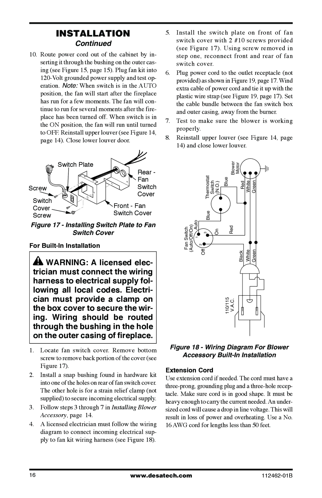
Figure 17 - Installing Switch Plate to Fan
Switch Cover
For Built-In Installation
![]() WARNING: A licensed elec- trician must connect the wiring harness to electrical supply fol- lowing all local codes. Electri- cian must provide a clamp on the box cover to secure the wir- ing. Wiring should be routed through the bushing in the hole on the outer casing of fireplace.
WARNING: A licensed elec- trician must connect the wiring harness to electrical supply fol- lowing all local codes. Electri- cian must provide a clamp on the box cover to secure the wir- ing. Wiring should be routed through the bushing in the hole on the outer casing of fireplace.
1.Locate fan switch cover. Remove bottom screw to remove back portion of the cover (see Figure 17).
2.Install a snap bushing found in hardware kit into one of the holes on rear of fan switch cover. The other hole is for a strain relief clamp (not supplied) to secure incoming electrical supply.
3.Follow steps 3 through 7 in Installing Blower Accessory, page 14.
4.A licensed electrician must follow the wiring diagram to connect incoming electrical sup- ply to fan kit wiring harness (see Figure 18).
5.Install the switch plate on front of fan switch cover with 2 #10 screws provided (see Figure 17). Using screw removed in step one, reconnect front and rear of fan switch cover.
6.Plug power cord to the outlet receptacle (not provided) as shown in Figure 19, page 17. Wind extra cable of power cord and tie it up with the plastic wire strap (see Figure 19, page 17). Set the cable bundle between the fan switch box and outer casing, away from the burner.
7.Test to make sure the blower is working properly.
8.Reinstall upper louver (see Figure 14, page 14) and close lower louver.
|
| Thermostat |
| Blower | Motor |
|
| |
|
| Switch (N.O.) | Blue | Red | White | Green | ||
| Auto | Blue |
|
|
|
|
| |
SwitchFan (Auto/Off/On) | Off | On | Red | Black | White | Green | ||
1 | ||||||||
|
| 3 |
|
|
|
|
| |
|
| 2 |
|
|
|
|
|
110/115 V.A.C.
Figure 18 - Wiring Diagram For Blower
Accessory Built-In Installation
Extension Cord
Use extension cord if needed. The cord must have a
16 | www.desatech.com |