OWNER’S MANUAL
INSTALLATION
Continued
3.Carefully set firebox in front of rough opening with back of firebox inside wall opening. IMPORTANT: If install- ing Brass Trim Kit GA6091 or GA6092, see instructions included with brass trim accessory. You must install shoulder screws from brass trim kit now.
4.Carefully insert firebox into rough opening.
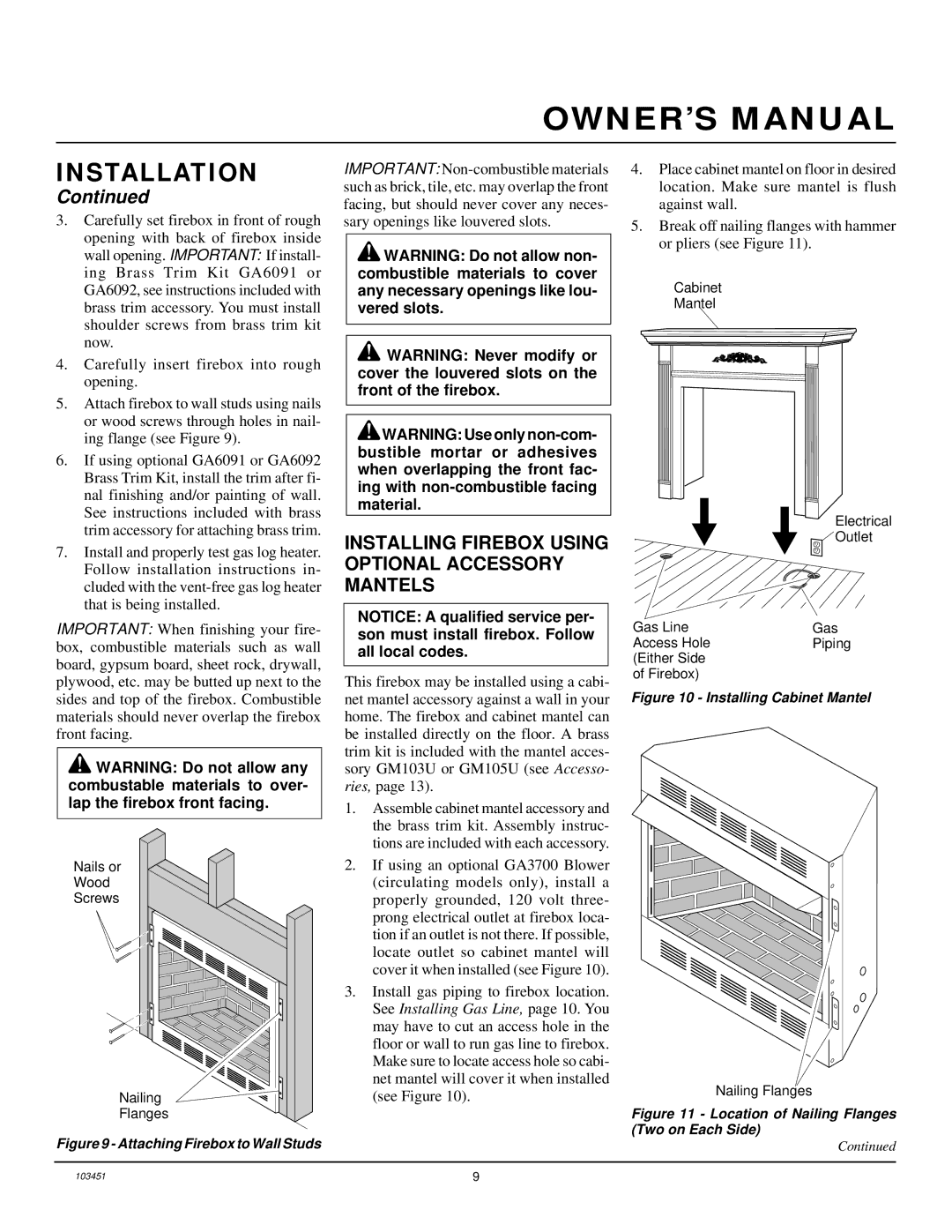
5.Attach firebox to wall studs using nails or wood screws through holes in nail- ing flange (see Figure 9).
6.If using optional GA6091 or GA6092 Brass Trim Kit, install the trim after fi- nal finishing and/or painting of wall. See instructions included with brass trim accessory for attaching brass trim.
7.Install and properly test gas log heater. Follow installation instructions in- cluded with the
IMPORTANT: When finishing your fire- box, combustible materials such as wall board, gypsum board, sheet rock, drywall, plywood, etc. may be butted up next to the sides and top of the firebox. Combustible materials should never overlap the firebox front facing.
![]() WARNING: Do not allow any combustable materials to over- lap the firebox front facing.
WARNING: Do not allow any combustable materials to over- lap the firebox front facing.
Nails or
Wood
Screws
Nailing
Flanges
Figure 9 - Attaching Firebox to Wall Studs
IMPORTANT:
![]() WARNING: Do not allow non- combustible materials to cover any necessary openings like lou- vered slots.
WARNING: Do not allow non- combustible materials to cover any necessary openings like lou- vered slots.
![]() WARNING: Never modify or cover the louvered slots on the front of the firebox.
WARNING: Never modify or cover the louvered slots on the front of the firebox.
![]() WARNING: Use only
WARNING: Use only
INSTALLING FIREBOX USING OPTIONAL ACCESSORY MANTELS
NOTICE: A qualified service per- son must install firebox. Follow all local codes.
This firebox may be installed using a cabi- net mantel accessory against a wall in your home. The firebox and cabinet mantel can be installed directly on the floor. A brass trim kit is included with the mantel acces- sory GM103U or GM105U (see Accesso- ries, page 13).
1.Assemble cabinet mantel accessory and the brass trim kit. Assembly instruc- tions are included with each accessory.
2.If using an optional GA3700 Blower (circulating models only), install a properly grounded, 120 volt three- prong electrical outlet at firebox loca- tion if an outlet is not there. If possible, locate outlet so cabinet mantel will cover it when installed (see Figure 10).
3.Install gas piping to firebox location. See Installing Gas Line, page 10. You may have to cut an access hole in the floor or wall to run gas line to firebox. Make sure to locate access hole so cabi- net mantel will cover it when installed (see Figure 10).
4.Place cabinet mantel on floor in desired location. Make sure mantel is flush against wall.
5.Break off nailing flanges with hammer or pliers (see Figure 11).
Cabinet
Mantel
Electrical
![]() Outlet
Outlet
Gas Line | Gas |
Access Hole | Piping |
(Either Side |
|
of Firebox) |
|
Figure 10 - Installing Cabinet Mantel
Nailing Flanges
Figure 11 - Location of Nailing Flanges (Two on Each Side)
Continued
103451 | 9 |
