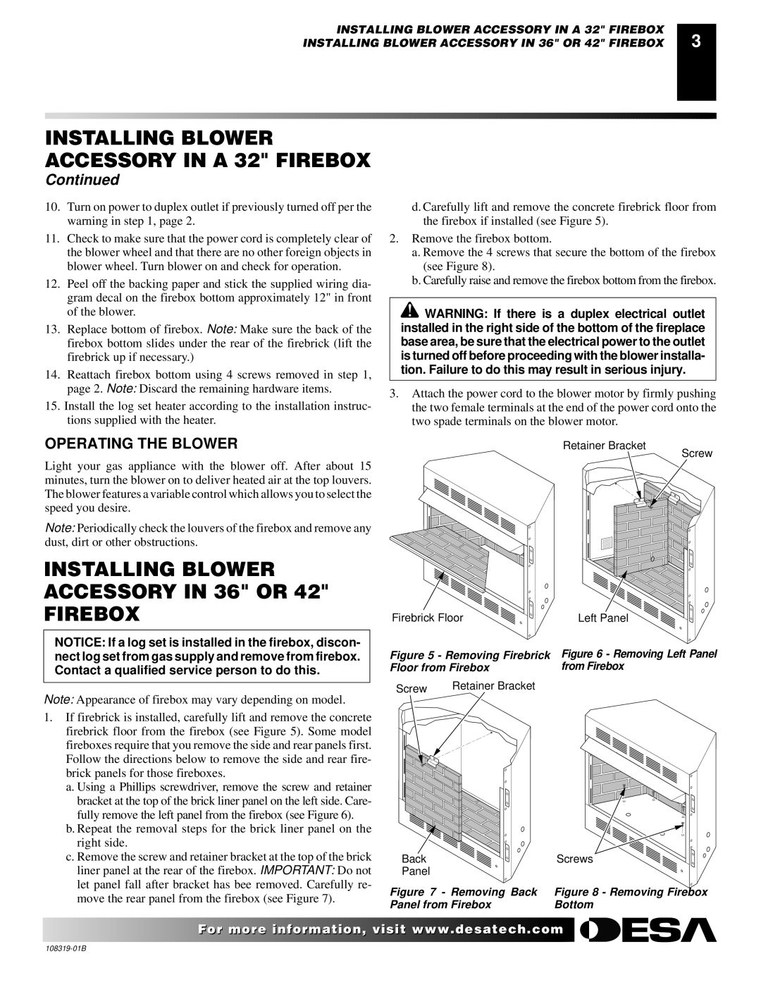
Ga3750a specifications
Desa GA3750A is a state-of-the-art technological solution designed for enhanced gas management in various applications. Built with user-friendly features and advanced mechanics, the GA3750A stands out in the market for its efficiency and reliability.One of the main features of the Desa GA3750A is its efficient gas control mechanism. It is equipped with a high-precision pressure regulator that ensures stable and consistent gas flow. This mechanism is essential for applications requiring precise gas consumption, such as industrial processes and commercial kitchens. It minimizes wastage while maximizing performance efficiency.
The GA3750A utilizes cutting-edge materials, ensuring durability and longevity. Its corrosion-resistant construction not only prolongs the lifespan of the device but also makes it suitable for use in harsh environments. Whether in high-humidity areas or exposed to corrosive substances, the GA3750A maintains its integrity, delivering reliable service over time.
In terms of technology, the GA3750A incorporates smart monitoring systems that provide real-time data on gas usage. This feature allows users to track consumption patterns, offering insights that can lead to optimized operations and cost savings. The integration of IoT connectivity means that this device can be easily connected to advanced monitoring systems, enabling remote access and control.
Moreover, safety is prioritized in the design of the GA3750A. Equipped with multi-layer safety features, it includes automatic shut-off valves and leak detection sensors. In the event of a malfunction or detected leak, these safety measures activate to prevent potential hazards, ensuring that users can operate with peace of mind.
The GA3750A is also designed for ease of installation and maintenance. Its modular construction facilitates simple setup, and the components can be easily accessed for routine checks or repairs. This consideration for user convenience significantly reduces downtime and maintenance costs.
Overall, the Desa GA3750A embodies a blend of advanced technology and practical features, making it an essential tool for gas management in industrial and commercial settings. With its focus on efficiency, durability, and safety, the GA3750A is a market leader that meets the demands of modern applications effectively.

