INSTALLING BLOWER ACCESSORY IN 36" OR 42" FIREBOX INSTALLING BLOWER ACCESSORY IN MODEL SVFBC FREESTANDING STOVE

5

INSTALLING BLOWER ACCESSORY IN 36" OR 42"

FIREBOX

Continued

b. If your firebox installation is recessed and/or pre-wired, plug the power cord into the duplex outlet provided. Refer to your firebox owner’s manual for instructions on wiring the duplex outlet.

12.Check to make sure that the power cord is completely clear of the blower wheel and that there are no other foreign objects in blower wheel. Turn blower on and check for operation. Turn blower off by turning knob fully counter-clockwise before continuing.

CAUTION: Never touch the blower wheel while in operation.

13.Peel off the backing paper and stick the supplied wiring dia- gram decal on the firebox bottom approximately 12" in front of the blower (see Figure 12, page 4).

14.Replace and reattach firebox bottom using 4 screws removed in step 2 (see Figure 8, page 3).

15.If previously removed, carefully replace the firebrick side pan- els and/or floor in the firebox (see Figures 5-7, page 3).

16.Install the log set heater according to the installation instruc- tions supplied with the heater.

WARNING: A qualified service person must install heater. Follow all local codes.

Note: Discard the remaining hardware items.

INSTALLING BLOWER ACCESSORY IN MODEL SVFBC FREESTANDING STOVE

NOTICE: Shut off gas heater during the following blower installation.

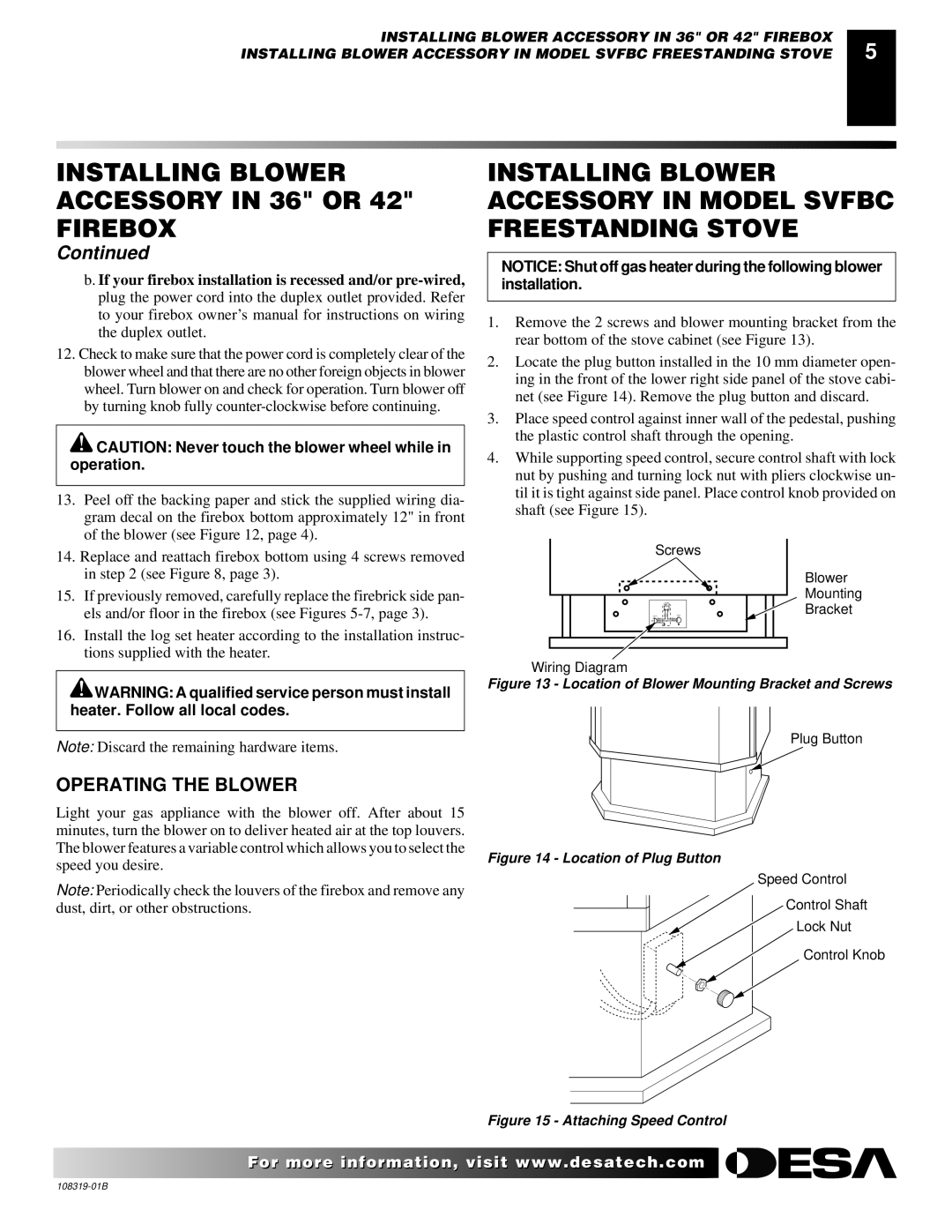
1.Remove the 2 screws and blower mounting bracket from the rear bottom of the stove cabinet (see Figure 13).

2.Locate the plug button installed in the 10 mm diameter open- ing in the front of the lower right side panel of the stove cabi- net (see Figure 14). Remove the plug button and discard.

3.Place speed control against inner wall of the pedestal, pushing the plastic control shaft through the opening.

4.While supporting speed control, secure control shaft with lock nut by pushing and turning lock nut with pliers clockwise un- til it is tight against side panel. Place control knob provided on shaft (see Figure 15).

Screws

Blower

Mounting

Bracket

Wiring Diagram

Figure 13 - Location of Blower Mounting Bracket and Screws

Plug Button

OPERATING THE BLOWER

Light your gas appliance with the blower off. After about 15 minutes, turn the blower on to deliver heated air at the top louvers. The blower features a variable control which allows you to select the

speed you desire.

Figure 14 - Location of Plug Button


Note: Periodically check the louvers of the firebox and remove any


dust, dirt, or other obstructions.


Speed Control

Control Shaft

Lock Nut

Control Knob

Figure 15 - Attaching Speed Control

For more information, visit www.desatech.com

108319-01B

Page 5
Image 5
Desa Ga3750a installation instructions Speed you desire

Ga3750a specifications

Desa GA3750A is a state-of-the-art technological solution designed for enhanced gas management in various applications. Built with user-friendly features and advanced mechanics, the GA3750A stands out in the market for its efficiency and reliability.

One of the main features of the Desa GA3750A is its efficient gas control mechanism. It is equipped with a high-precision pressure regulator that ensures stable and consistent gas flow. This mechanism is essential for applications requiring precise gas consumption, such as industrial processes and commercial kitchens. It minimizes wastage while maximizing performance efficiency.

The GA3750A utilizes cutting-edge materials, ensuring durability and longevity. Its corrosion-resistant construction not only prolongs the lifespan of the device but also makes it suitable for use in harsh environments. Whether in high-humidity areas or exposed to corrosive substances, the GA3750A maintains its integrity, delivering reliable service over time.

In terms of technology, the GA3750A incorporates smart monitoring systems that provide real-time data on gas usage. This feature allows users to track consumption patterns, offering insights that can lead to optimized operations and cost savings. The integration of IoT connectivity means that this device can be easily connected to advanced monitoring systems, enabling remote access and control.

Moreover, safety is prioritized in the design of the GA3750A. Equipped with multi-layer safety features, it includes automatic shut-off valves and leak detection sensors. In the event of a malfunction or detected leak, these safety measures activate to prevent potential hazards, ensuring that users can operate with peace of mind.

The GA3750A is also designed for ease of installation and maintenance. Its modular construction facilitates simple setup, and the components can be easily accessed for routine checks or repairs. This consideration for user convenience significantly reduces downtime and maintenance costs.

Overall, the Desa GA3750A embodies a blend of advanced technology and practical features, making it an essential tool for gas management in industrial and commercial settings. With its focus on efficiency, durability, and safety, the GA3750A is a market leader that meets the demands of modern applications effectively.