SUN VALLEY STOVE COMPANY
INSTALLATION
Continued
We recommend that you install a sediment trap in supply line as shown in Figures 18 and 19, page 11. Locate sediment trap where it is within reach for cleaning. Install in piping system between fuel supply and heater. Locate sediment trap where trapped matter is not likely to freeze. A sediment trap traps moisture and contaminants. This keeps them from going into heater controls. If sediment trap is not installed or is in- stalled wrong, heater may not run properly.
![]() CAUTION: Avoid damage to regulator. Hold gas regulator with wrench when connecting it to gas piping and/or fittings.
CAUTION: Avoid damage to regulator. Hold gas regulator with wrench when connecting it to gas piping and/or fittings.
CHECKING GAS
CONNECTIONS
4.Check all joints of gas supply piping system. Apply mixture of liquid soap and water to gas joints. Bubbles form- ing show a leak.
5.Correct all leaks at once.
6.Reconnect heater and equipment shutoff valve to gas supply. Check re- connected fittings for leaks.
Test Pressures Equal To or Less Than 1/2 PSIG (3.5 kPa)
1.Close equipment shutoff valve (see Fig- ure 20).
2.Pressurize supply piping system by ei- ther using compressed air or opening main gas valve located on or near gas meter.
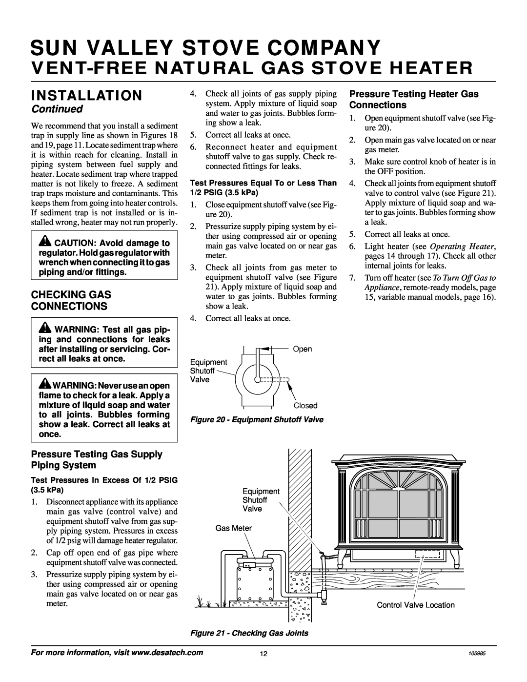
3.Check all joints from gas meter to equipment shutoff valve (see Figure 21). Apply mixture of liquid soap and water to gas joints. Bubbles forming show a leak.
4.Correct all leaks at once.
Pressure Testing Heater Gas Connections
1.Open equipment shutoff valve (see Fig- ure 20).
2.Open main gas valve located on or near gas meter.
3.Make sure control knob of heater is in the OFF position.
4.Check all joints from equipment shutoff valve to control valve (see Figure 21). Apply mixture of liquid soap and wa- ter to gas joints. Bubbles forming show a leak.
5.Correct all leaks at once.
6.Light heater (see Operating Heater, pages 14 through 17). Check all other internal joints for leaks.
7.Turn off heater (see To Turn Off Gas to Appliance,
![]() WARNING: Test all gas pip- ing and connections for leaks after installing or servicing. Cor- rect all leaks at once.
WARNING: Test all gas pip- ing and connections for leaks after installing or servicing. Cor- rect all leaks at once.
![]() WARNING: Never use an open flame to check for a leak. Apply a mixture of liquid soap and water to all joints. Bubbles forming show a leak. Correct all leaks at once.
WARNING: Never use an open flame to check for a leak. Apply a mixture of liquid soap and water to all joints. Bubbles forming show a leak. Correct all leaks at once.
Open
Equipment
Shutoff ![]()
Valve
Closed
Figure 20 - Equipment Shutoff Valve
Pressure Testing Gas Supply Piping System
Test Pressures In Excess Of 1/2 PSIG (3.5 kPa)
1.Disconnect appliance with its appliance main gas valve (control valve) and equipment shutoff valve from gas sup- ply piping system. Pressures in excess of 1/2 psig will damage heater regulator.
2.Cap off open end of gas pipe where equipment shutoff valve was connected.
3.Pressurize supply piping system by ei- ther using compressed air or opening main gas valve located on or near gas meter.
Equipment
Shutoff
Valve
Gas Meter
Control Valve Location |
Figure 21 - Checking Gas Joints
For more information, visit www.desatech.com | 12 | 105985 |