RJ45 And RJ70

PORTABLE FORCED AIR HEATERS

SERVICE

PROCEDURES

Continued

SPARK PLUG (RJ70)

1.

Remove upper shell (see Upper Shell


Removal, page 8).

2.

Remove fan (see Fan, page 8).

3.

Remove spark plug wire from spark plug.

4.

Remove spark plug from burner head


using 13/16" open-end wrench.

5.

Clean and regap spark plug electrodes

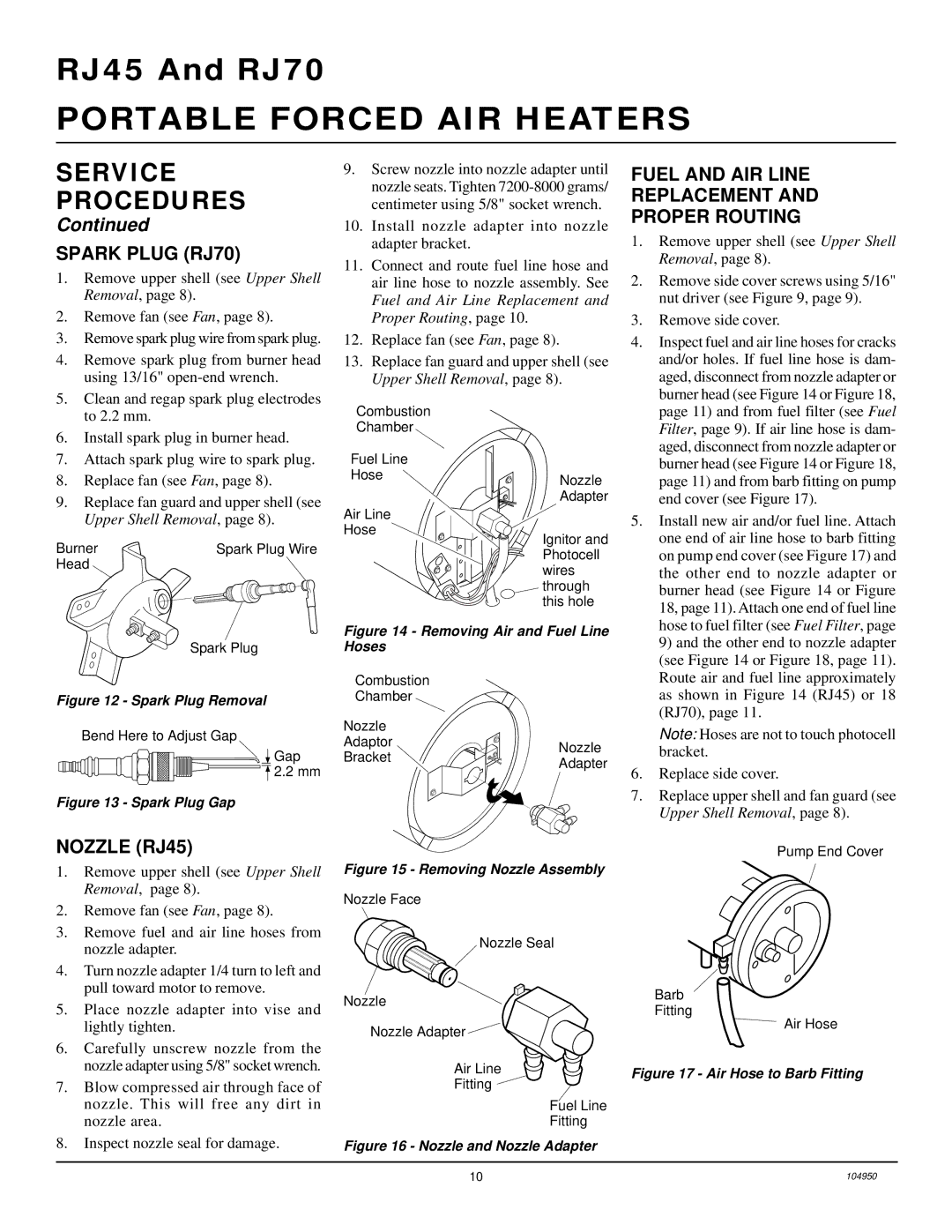
9.Screw nozzle into nozzle adapter until nozzle seats. Tighten 7200-8000 grams/ centimeter using 5/8" socket wrench.

10.Install nozzle adapter into nozzle adapter bracket.

11.Connect and route fuel line hose and air line hose to nozzle assembly. See Fuel and Air Line Replacement and Proper Routing, page 10.

12.Replace fan (see Fan, page 8).

13.Replace fan guard and upper shell (see Upper Shell Removal, page 8).

FUEL AND AIR LINE

REPLACEMENT AND

PROPER ROUTING

1.

Remove upper shell (see Upper Shell


Removal, page 8).

2.

Remove side cover screws using 5/16"


nut driver (see Figure 9, page 9).

3.

Remove side cover.

4.

Inspect fuel and air line hoses for cracks


and/or holes. If fuel line hose is dam-


aged, disconnect from nozzle adapter or


burner head (see Figure 14 or Figure 18,


to 2.2 mm.

6.

Install spark plug in burner head.

7.

Attach spark plug wire to spark plug.

8.

Replace fan (see Fan, page 8).

9.

Replace fan guard and upper shell (see


Upper Shell Removal, page 8).

Burner

Spark Plug Wire

Head


Combustion Chamber

Fuel Line

Hose

Air Line

Hose

Nozzle

Adapter

Ignitor and

Photocell wires

through this hole

page 11) and from fuel filter (see Fuel

Filter, page 9). If air line hose is dam-

aged, disconnect from nozzle adapter or

burner head (see Figure 14 or Figure 18,

page 11) and from barb fitting on pump

end cover (see Figure 17).

5. Install new air and/or fuel line. Attach

one end of air line hose to barb fitting

on pump end cover (see Figure 17) and

the other end to nozzle adapter or

burner head (see Figure 14 or Figure

18, page 11). Attach one end of fuel line

hose to fuel filter (see Fuel Filter, page

Spark Plug

Figure 12 - Spark Plug Removal

Bend Here to Adjust Gap

Gap 2.2 mm

Figure 13 - Spark Plug Gap

Figure 14 - Removing Air and Fuel Line Hoses

Combustion

Chamber

Nozzle


Adaptor

Nozzle

Bracket

Adapter


9) and the other end to nozzle adapter

(see Figure 14 or Figure 18, page 11).

Route air and fuel line approximately

as shown in Figure 14 (RJ45) or 18

(RJ70), page 11.

Note: Hoses are not to touch photocell bracket.

6.Replace side cover.

7.Replace upper shell and fan guard (see Upper Shell Removal, page 8).

NOZZLE (RJ45)

1.Remove upper shell (see Upper Shell Removal, page 8).

2.Remove fan (see Fan, page 8).

3.Remove fuel and air line hoses from nozzle adapter.

4.Turn nozzle adapter 1/4 turn to left and pull toward motor to remove.

5.Place nozzle adapter into vise and lightly tighten.

6.Carefully unscrew nozzle from the nozzle adapter using 5/8" socket wrench.

7.Blow compressed air through face of nozzle. This will free any dirt in nozzle area.

8.Inspect nozzle seal for damage.

Figure 15 - Removing Nozzle Assembly

Nozzle Face

Nozzle Seal

Nozzle

Nozzle Adapter

Air Line

Fitting

Fuel Line

Fitting

Figure 16 - Nozzle and Nozzle Adapter

Pump End Cover

Barb

Fitting

Air Hose

Figure 17 - Air Hose to Barb Fitting

10

104950

Page 10
Image 10
Desa owner manual Spark Plug RJ70, Fuel and AIR Line Replacement Proper Routing, Nozzle RJ45

RJ70, RJ45 specifications

Desa RJ45 and RJ70 are two prominent connector types commonly used in networking and telecommunications. They serve as vital components in facilitating communication and data transfer over various networks, playing crucial roles in both home and commercial environments.

The RJ45 connector is perhaps the most recognized of the two, primarily used in Ethernet networks. Its standard design accommodates eight pins, enabling the connection of twisted-pair cables, most notably Category 5e, Category 6, and higher. This widespread acceptance can be attributed to its ability to support high-speed data transfer rates, with contemporary setups allowing speeds up to 10 Gbps over short distances. Key features of the RJ45 connector include its simple plug-and-play functionality, which streamlines installation and enhances user experience.

In comparison, the RJ70 connector is less common but is engineered for specific applications within telecommunications. This connector is designed with four pins, mainly used with telephone systems and low-speed data transmission. The RJ70 is particularly notable for its application in modular voice communication, where it is employed to connect telephones and to facilitate basic data connections.

Both RJ45 and RJ70 utilize differential signaling to enhance performance and reduce interference, which is vital in densely populated electronic environments. Furthermore, the connectors’ compact size aids in efficient space management, an important characteristic in data centers and telecom applications.

The physical structure of these connectors includes a locking mechanism to secure connections firmly, ensuring stability during operation. Additionally, RJ45 connectors typically come in shielded (STP) and unshielded (UTP) variations, offering options for users based on their environmental needs to mitigate electromagnetic interference.

In summary, Desa RJ45 and RJ70 connectors are integral to modern networking technologies. RJ45 connectors dominate Ethernet installations with their high-speed capabilities and versatility, while RJ70 connectors fulfill niche roles in voice communication systems. Understanding the features and technologies behind these connectors is essential for professionals in telecommunications and networking, ensuring optimal setup and performance in diverse applications. The ongoing evolution in networking demands keeps these connector types relevant, adapting to the increasing bandwidth requirements and technological advancements in data communication.