VENT-FREE NATURAL GAS PEDESTAL STOVE
OPERATING
HEATER
Continued
LIGHTING
INSTRUCTIONS
NOTICE: During initial operation of new heater, burning logs will give off a
1.STOP! Read the safety information, page 11, column 3.
2.Make sure equipment shutoff valve is fully open.
3. Turn control knob clockwise Clockwise![]() to the OFF position.
to the OFF position.
4.Wait five (5) minutes to clear out any gas. Then smell for gas, including near the floor. If you smell gas, STOP! Follow “B” in the safety in- formation, page 11, column 3. If you don’t smell gas, go to the next step.
5.Turn control knob counterclockwise
![]() C-clockwise
C-clockwise
Press in control knob for five (5) sec- onds (see Figure 17). Note: You may be running this heater for the first time after hooking up to gas supply. If so, the control knob may need to be pressed in for 30 seconds or less. This will allow air to bleed from the gas system.
6.With control knob pressed in, press and release ignitor button. This will light pilot. The pilot is attached to the front burner. If needed, keep press- ing ignitor button until pilot lights.
Note: If pilot does not stay lit, con- tact a qualified service person or gas supplier for repairs. Until repairs are made, light pilot with match. To light pilot with match, see Manual Light- ing Procedure.
| Ignitor Button |
|
| Control Knob | |||||||
|
|
|
|
|
|
|
|
|
|
|
|
|
|
|
|
|
|
|
|
|
|
|
|
|
|
|
|
|
|
|
|
|
|
|
|
|
|
|
|
|
|
|
|
|
|
|
|
Figure 17- Control Knob and Ignitor Button Location
7.Keep control knob pressed in for 30 seconds after lighting pilot. After 30 seconds, release control knob.
•If control knob does not pop out when released, contact a qualified service person or gas supplier for repairs.
Note: If pilot goes out, repeat steps 3 through 7.This heater has a safety inter- lock system. Wait one (1) minute for sys- tem to reset before lighting pilot again.
8.Turn control knob counterclockwise
![]() C-clockwise
C-clockwise
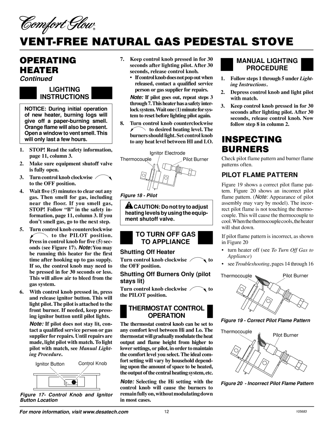
Ignitor Electrode
Thermocouple | Pilot Burner |
Figure 18 - Pilot
![]() CAUTION: Do not try to adjust heating levels by using the equip- ment shutoff valve.
CAUTION: Do not try to adjust heating levels by using the equip- ment shutoff valve.
TO TURN OFF GAS
TO APPLIANCE
Shutting Off Heater
Turn control knob clockwise Clockwise![]() to the OFF position.
to the OFF position.
Shutting Off Burners Only (pilot stays lit)
Turn control knob clockwise Clockwise![]() to the PILOT position.
to the PILOT position.
THERMOSTAT CONTROL
OPERATION
The thermostat control knob can be set to any comfort level between Hi and Lo. The thermostat will gradually modulate the heat output and flame height from higher to lower settings, or pilot, in order to maintain the comfort level you select. The ideal com- fort setting will vary by household depend- ing upon the amount of space to be heated, the output of the central heating system, etc.
Note: Selecting the Hi setting with the control knob will cause the burners to remain fully on, without modulating down in most cases.
MANUAL LIGHTING
PROCEDURE
1.Follow steps 1 through 5 under Light- ing Instructions.
2.Depress control knob and light pilot with match.
3.Keep control knob pressed in for 30 seconds after lighting pilot. After 30 seconds, release control knob. Now follow step 8 in column 2.
INSPECTING
BURNERS
Check pilot flame pattern and burner flame patterns often.
PILOT FLAME PATTERN
Figure 19 shows a correct pilot flame pat- tern. Figure 20 shows an incorrect pilot flame pattern. (Note: Appearance of pilot assembly may vary by model). The incor- rect pilot flame is not touching the thermo- couple. This will cause the thermocouple to cool. When the thermocouple cools, the heater will shut down.
If pilot flame pattern is incorrect, as shown in Figure 20
•turn heater off (see To Turn Off Gas to Appliance)
•seeTroubleshooting, pages 14 through 16
Thermocouple | Pilot Burner |
Figure 19 - Correct Pilot Flame Pattern
Thermocouple
Pilot Burner
Figure 20 - Incorrect Pilot Flame Pattern
For more information, visit www.desatech.com | 12 | 105683 |