Manuals
/
Desa
/
Household Appliance
/
Indoor Fireplace
Desa
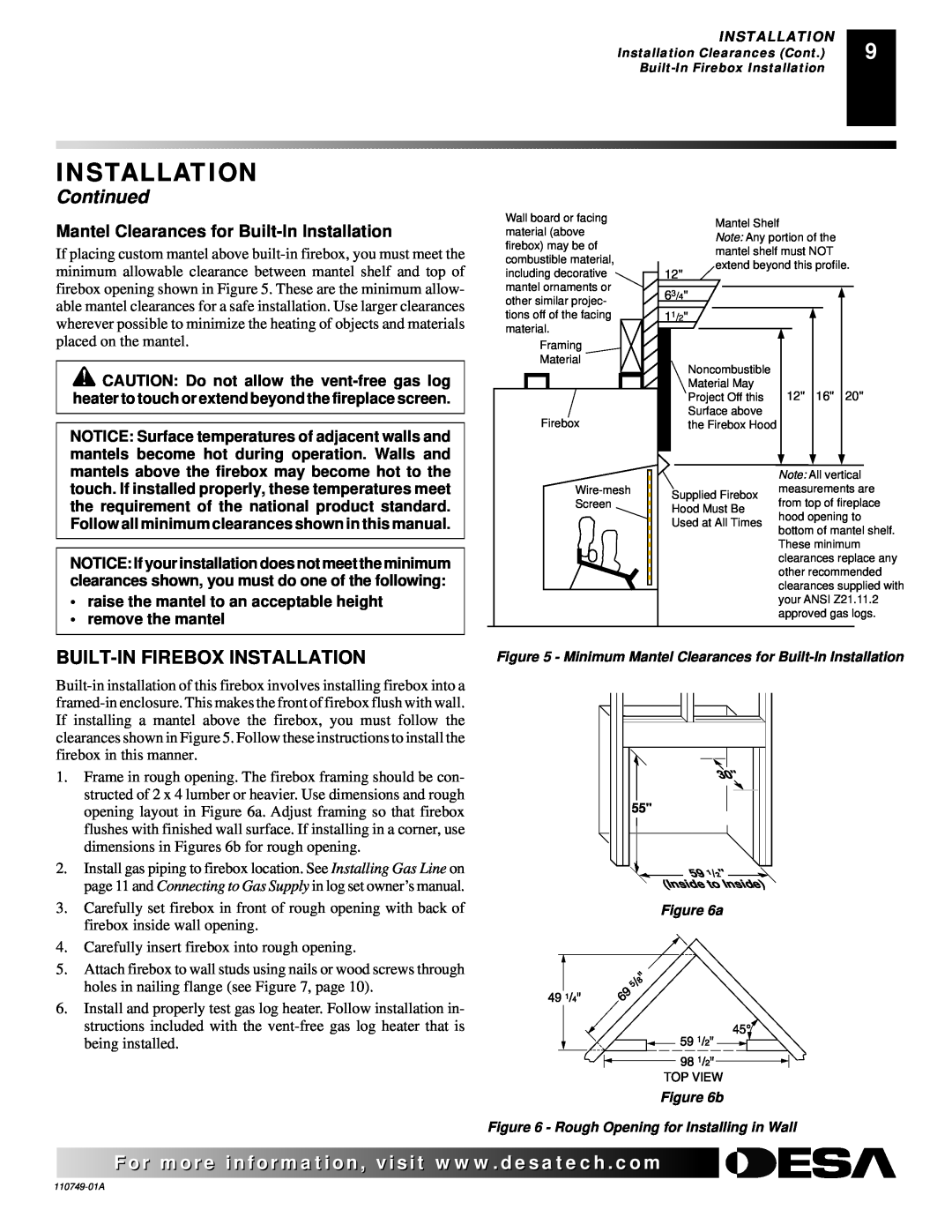
V50S Continued, Built-Infirebox Installation, Mantel Clearances for Built-InInstallation
Models:
V50S
V50SH
VFB50NC
1
9
18
18
Download
18 pages
32.6 Kb
6
7
8
9
10
11
12
13
Specification
Install
Parts list
Warranty
Accessories
Safety
Page 9
Image 9
Page 8
Page 10
Page 9
Image 9
Page 8
Page 10
Contents
Save this manual for future
UNVENTED VENT-FREE UNIVERSAL FIREBOX
TM OWNER’S OPERATION AND INSTALLATION MANUAL
V50S, V50SH, and VFB50NC Vent-FreeFireboxes
TABLE OF CONTENTS
SAFETY INFORMATION
WARNINGS
LOCAL CODES
PRODUCT FEATURES
LOCATING FIREBOX
Continued
PRODUCT SPECIFICATIONS
PRODUCT SPECIFICATIONS
Figure 1 - Firebox Dimensions
Firebox Top View
PROVIDING ADEQUATE VENTILATION
AIR FOR COMBUSTION AND VENTILATION
AIR FOR COMBUSTION AND VENTILATION
Continued
AIR FOR COMBUSTION AND VENTILATION
Continued
AIR FOR COMBUSTION AND VENTILATION
VENTILATION AIR
Ventilation Air From Inside Building
INSTALLATION CLEARANCES
INSTALLATION
BUILT-INFIREBOX INSTALLATION
INSTALLATION
Mantel Clearances for Built-InInstallation
Continued
INSTALLATION
Continued
1.Assemble cabinet mantel as instructed
INSTALLING GAS LINE
INSTALLATION
INSTALLING FIREPLACE HOOD AND SCREEN
INSTALLATION
ILLUSTRATED PARTS BREAKDOWN
ILLUSTRATED PARTS BREAKDOWN
24 25 23 38 32 36 37
11 12
PARTS LIST
PARTS LIST
PART
PART
ACCESSORIES
TECHNICAL SERVICE
REPLACEMENT PARTS
H50B - 50 Hood - Brushed Brass
OWNERS REGISTRATION FORM
TAPE
Postage Required
TAPE
2701 Industrial Drive P.O. Box Bowling Green, KY
Page
NOT A UPC
WARRANTY INFORMATION
Model Serial No Date Purchased
2701 Industrial Drive P.O. Box Bowling Green, KY
Top
Page
Image
Contents