58 | MTM5400 Mobile Terminal Installation Manual | INSTALLATION |
|
|
|
Connectors and Pin Assignment of the Radio
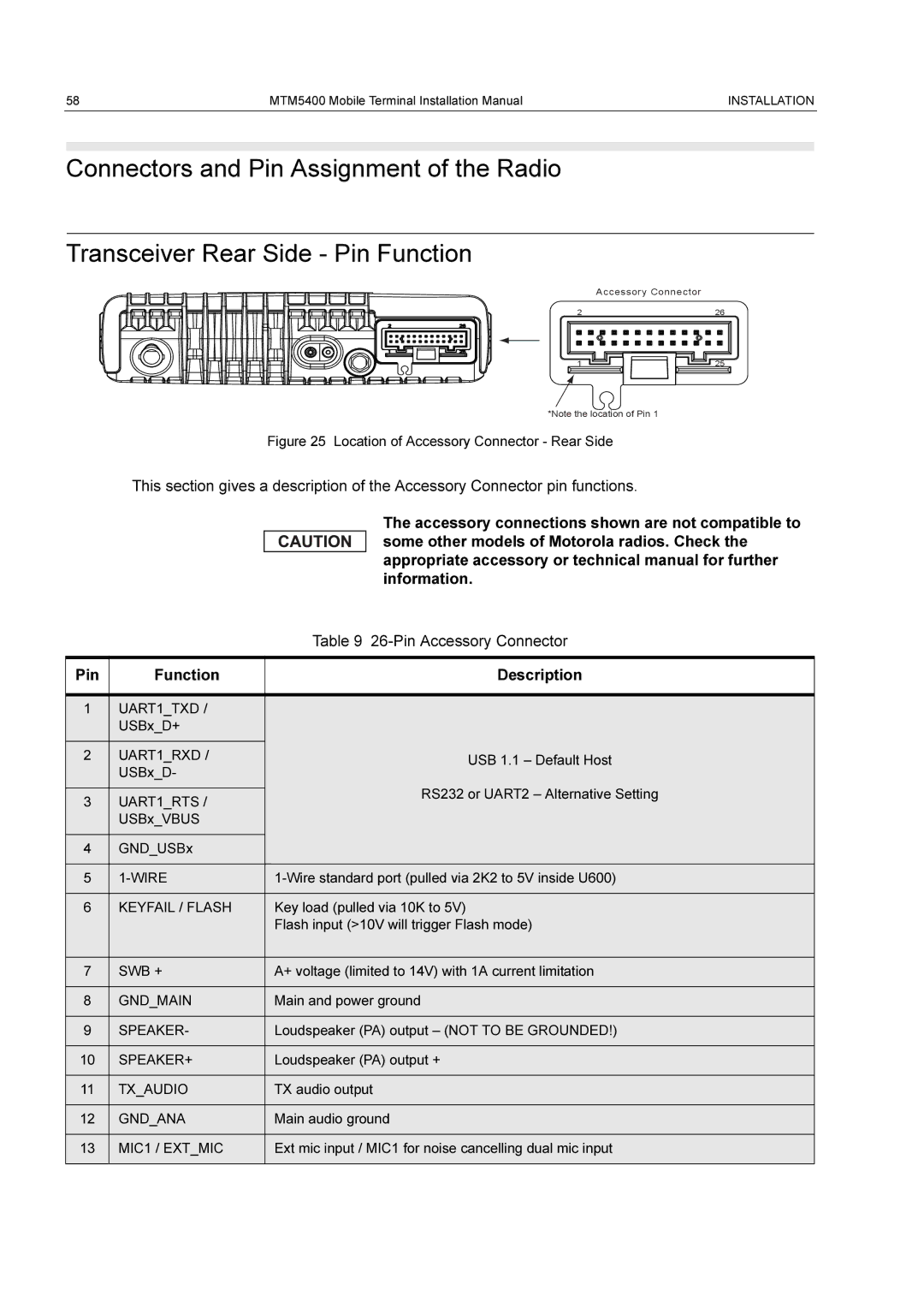
Transceiver Rear Side - Pin Function
Accessory Connector
2 | 26 |
1 | 25 |
*Note the location of Pin 1
Figure 25 Location of Accessory Connector - Rear Side
This section gives a description of the Accessory Connector pin functions.
The accessory connections shown are not compatible to some other models of Motorola radios. Check the appropriate accessory or technical manual for further information.
|
| Table 9 | |
|
|
| |
Pin | Function | Description | |
|
|
| |
1 | UART1_TXD / |
| |
| USBx_D+ |
| |
|
|
| |
2 | UART1_RXD / | USB 1.1 – Default Host | |
| USBx_D- | ||
|
| ||
|
| RS232 or UART2 – Alternative Setting | |
3 | UART1_RTS / | ||
| |||
| USBx_VBUS |
| |
|
|
| |
4 | GND_USBx |
| |
|
|
| |
5 |
| ||
|
|
| |
6 | KEYFAIL / FLASH | Key load (pulled via 10K to 5V) | |
|
| Flash input (>10V will trigger Flash mode) | |
|
|
| |
7 | SWB + | A+ voltage (limited to 14V) with 1A current limitation | |
|
|
| |
8 | GND_MAIN | Main and power ground | |
|
|
| |
9 | SPEAKER- | Loudspeaker (PA) output – (NOT TO BE GROUNDED!) | |
|
|
| |
10 | SPEAKER+ | Loudspeaker (PA) output + | |
|
|
| |
11 | TX_AUDIO | TX audio output | |
|
|
| |
12 | GND_ANA | Main audio ground | |
|
|
| |
13 | MIC1 / EXT_MIC | Ext mic input / MIC1 for noise cancelling dual mic input | |
|
|
|