INSTALLATIONMTM5400 Mobile Terminal Installation Manual59
|
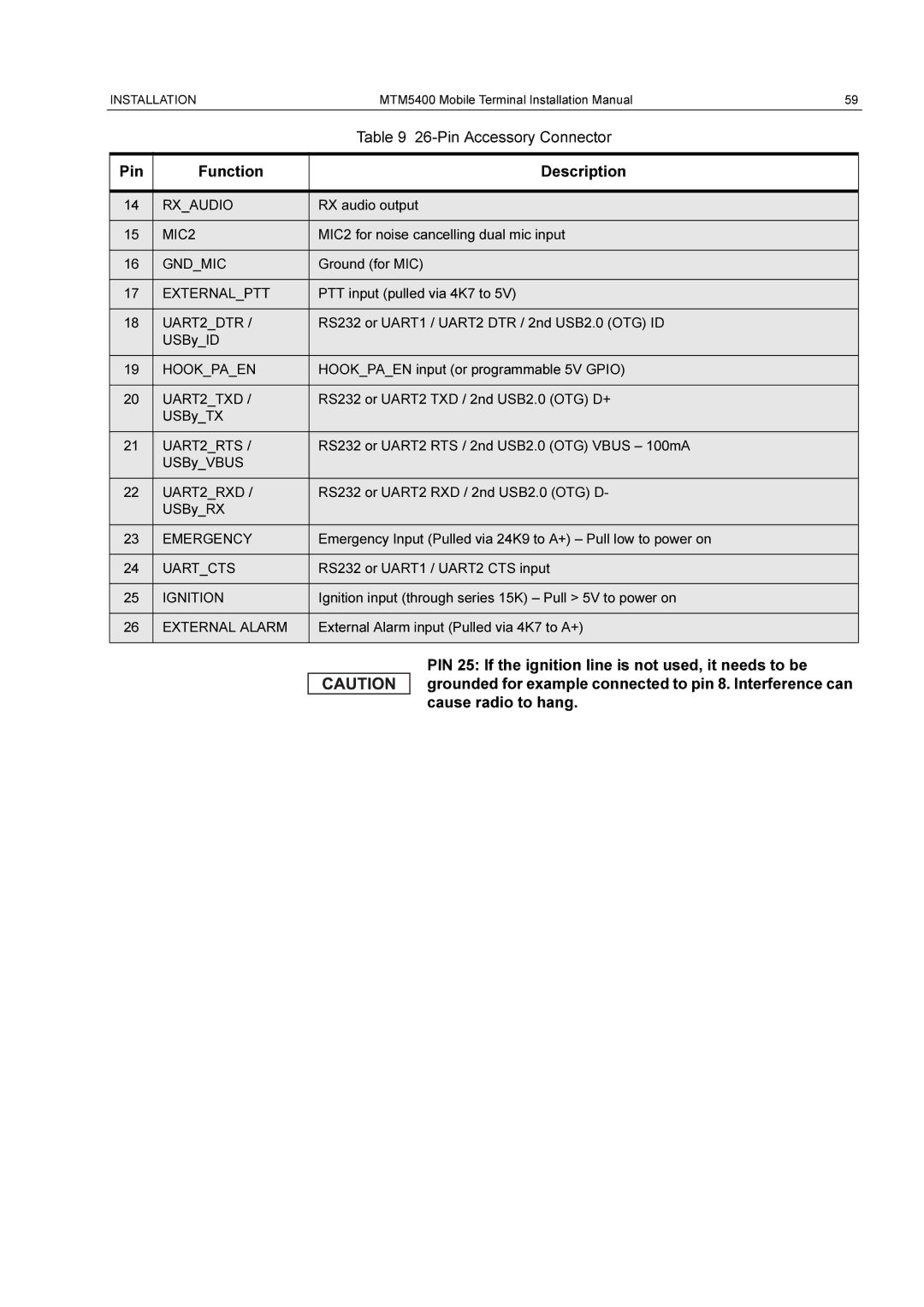
| Table 9 |
|
|
|
Pin | Function | Description |
|
|
|
14 | RX_AUDIO | RX audio output |
|
|
|
15 | MIC2 | MIC2 for noise cancelling dual mic input |
|
|
|
16 | GND_MIC | Ground (for MIC) |
|
|
|
17 | EXTERNAL_PTT | PTT input (pulled via 4K7 to 5V) |
|
|
|
18 | UART2_DTR / | RS232 or UART1 / UART2 DTR / 2nd USB2.0 (OTG) ID |
| USBy_ID |
|
|
|
|
19 | HOOK_PA_EN | HOOK_PA_EN input (or programmable 5V GPIO) |
|
|
|
20 | UART2_TXD / | RS232 or UART2 TXD / 2nd USB2.0 (OTG) D+ |
| USBy_TX |
|
|
|
|
21 | UART2_RTS / | RS232 or UART2 RTS / 2nd USB2.0 (OTG) VBUS – 100mA |
| USBy_VBUS |
|
|
|
|
22 | UART2_RXD / | RS232 or UART2 RXD / 2nd USB2.0 (OTG) D- |
| USBy_RX |
|
|
|
|
23 | EMERGENCY | Emergency Input (Pulled via 24K9 to A+) – Pull low to power on |
|
|
|
24 | UART_CTS | RS232 or UART1 / UART2 CTS input |
|
|
|
25 | IGNITION | Ignition input (through series 15K) – Pull > 5V to power on |
|
|
|
26 | EXTERNAL ALARM | External Alarm input (Pulled via 4K7 to A+) |
|
|
|
PIN 25: If the ignition line is not used, it needs to be grounded for example connected to pin 8. Interference can cause radio to hang.
