INSTALLATION | MTM5400 Mobile Terminal Installation Manual | 53 |
|
|
|
Service
The junction box PCB is not repairable. Please order a new junction box as necessary.
Connections
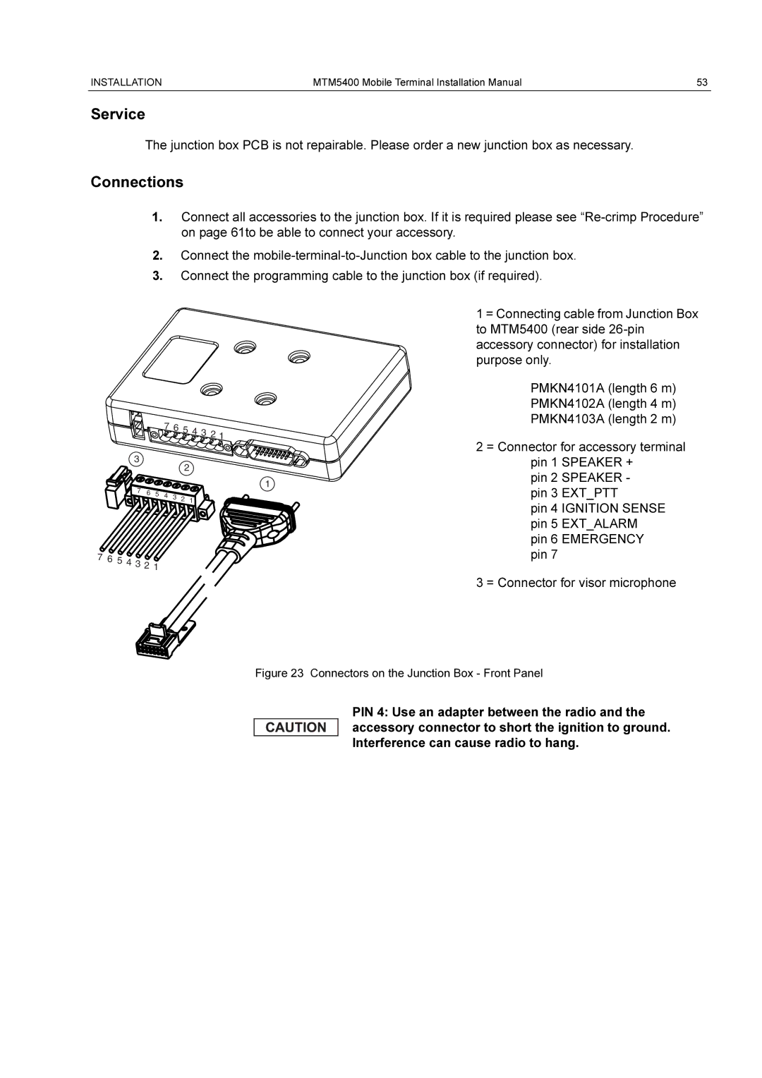
1.Connect all accessories to the junction box. If it is required please see
2.Connect the
3.Connect the programming cable to the junction box (if required).
|
|
|
|
|
|
|
| 1 = Connecting cable from Junction Box |
|
|
|
|
|
|
|
| to MTM5400 (rear side |
|
|
|
|
|
|
|
| accessory connector) for installation |
|
|
|
|
|
|
|
| purpose only. |
|
|
|
|
|
|
|
| PMKN4101A (length 6 m) |
|
|
|
|
|
|
|
| PMKN4102A (length 4 m) |
|
|
|
| 7 | 6 | 5 4 3 2 1 |
| PMKN4103A (length 2 m) |
|
|
|
|
|
| |||
|
|
|
|
|
|
|
| |
| 3 |
|
|
|
|
|
| 2 = Connector for accessory terminal |
|
|
|
|
| 2 |
| pin 1 SPEAKER + | |
|
|
|
|
|
|
| ||
|
|
|
|
|
|
| pin 2 SPEAKER - | |
|
|
|
|
|
|
| 1 | |
| 7 | 6 |
|
|
|
| pin 3 EXT_PTT | |
| 5 | 4 | 3 2 1 |
| ||||
|
|
| ||||||
|
|
|
|
|
|
| ||
|
|
|
|
|
|
|
| pin 4 IGNITION SENSE |
|
|
|
|
|
|
|
| pin 5 EXT_ALARM |
|
|
|
|
|
|
|
| pin 6 EMERGENCY |
7 6 5 | 4 3 2 1 |
|
|
|
| pin 7 | ||
|
|
|
|
|
| |||
|
|
|
|
|
|
|
| 3 = Connector for visor microphone |
Figure 23 Connectors on the Junction Box - Front Panel
PIN 4: Use an adapter between the radio and the accessory connector to short the ignition to ground. Interference can cause radio to hang.