INSTALLATION | MTM5400 Mobile Terminal Installation Manual | 29 |
|
|
|
In cases of blown fuses, replace ONLY with those of identical value.
NEVER insert ones of different values.
Installation Procedure
Begin the DC power cable installation as follows:
1.Determine a routing plan, keeping in mind where the terminal is to be mounted and make sure that the cable does not rest on sharp edges.
Improper handling with the power cable may cause shorting to ground. Ensure that during terminal installation the power cable fuse is removed.
Make sure your power cable is not placed with the antenna in parallel. Interference can cause radio to hang.
2.Locate an existing hole with grommet in the vehicle fire wall, or use a 9.5 mm
Be very careful not to damage existing wires.
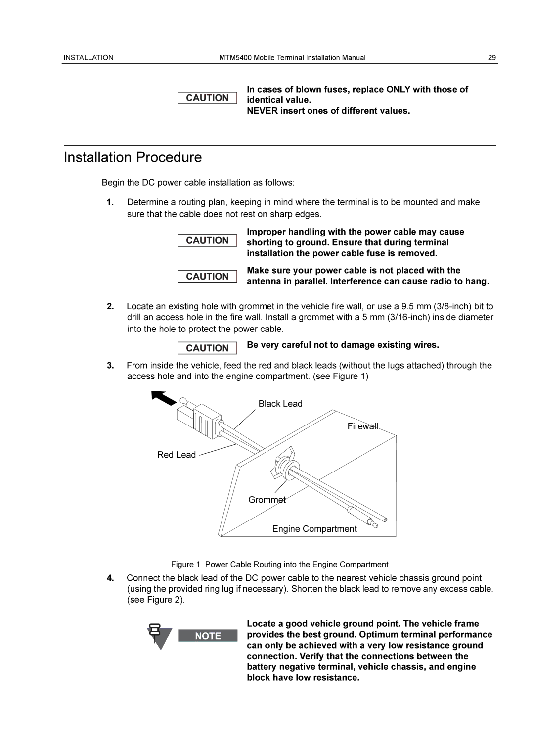
3.From inside the vehicle, feed the red and black leads (without the lugs attached) through the access hole and into the engine compartment. (see Figure 1)
Black Lead
Firewall
Red Lead ![]()
Grommet
Engine Compartment
Figure 1 Power Cable Routing into the Engine Compartment
4.Connect the black lead of the DC power cable to the nearest vehicle chassis ground point (using the provided ring lug if necessary). Shorten the black lead to remove any excess cable. (see Figure 2).
Locate a good vehicle ground point. The vehicle frame provides the best ground. Optimum terminal performance can only be achieved with a very low resistance ground connection. Verify that the connections between the battery negative terminal, vehicle chassis, and engine block have low resistance.