INSTALLATIONMTM5400 Mobile Terminal Installation Manual67
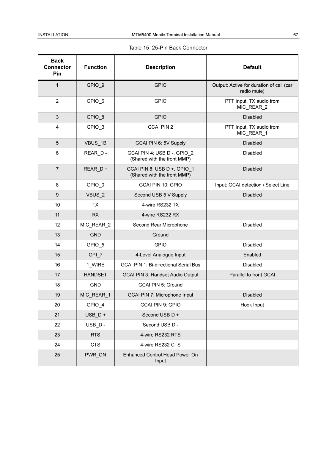
Table 15 25-Pin Back Connector
Back |
|
|
|
Connector | Function | Description | Default |
Pin |
|
|
|
|
|
|
|
1 | GPIO_9 | GPIO | Output: Active for duration of call (car |
|
|
| radio mute) |
|
|
|
|
2 | GPIO_6 | GPIO | PTT Input, TX audio from |
|
|
| MIC_REAR_2 |
|
|
|
|
3 | GPIO_8 | GPIO | Disabled |
|
|
|
|
4 | GPIO_3 | GCAI PIN 2 | PTT Input, TX audio from |
|
|
| MIC_REAR_1 |
|
|
|
|
5 | VBUS_1B | GCAI PIN 6: 5V Supply | Disabled |
|
|
|
|
6 | REAR_D - | GCAI PIN 4: USB D | Disabled |
|
| (Shared with the front MMP) |
|
|
|
|
|
7 | REAR_D + | GCAI PIN 8: USB D +, GPIO_1 | Disabled |
|
| (Shared with the front MMP) |
|
|
|
|
|
8 | GPIO_0 | GCAI PIN 10: GPIO | Input: GCAI detection / Select Line |
|
|
|
|
9 | VBUS_2 | Second USB 5 V Supply | Disabled |
|
|
|
|
10 | TX |
| |
|
|
|
|
11 | RX |
| |
|
|
|
|
12 | MIC_REAR_2 | Second Rear Microphone | Disabled |
|
|
|
|
13 | GND | Ground |
|
|
|
|
|
14 | GPIO_5 | GPIO | Disabled |
|
|
|
|
15 | GPI_7 | Enabled | |
|
|
|
|
16 | 1_WIRE | GCAI PIN 1: | Disabled |
|
|
|
|
17 | HANDSET | GCAI PIN 3: Handset Audio Output | Parallel to front GCAI |
|
|
|
|
18 | GND | GCAI PIN 5: Ground |
|
|
|
|
|
19 | MIC_REAR_1 | GCAI PIN 7: Microphone Input | Disabled |
|
|
|
|
20 | GPIO_4 | GCAI PIN 9: GPIO | Hook Input |
|
|
|
|
21 | USB_D + | Second USB D + |
|
|
|
|
|
22 | USB_D - | Second USB D - |
|
|
|
|
|
23 | RTS |
| |
|
|
|
|
24 | CTS |
| |
|
|
|
|
25 | PWR_ON | Enhanced Control Head Power On |
|
|
| Input |
|
|
|
|
|
