Pre-Installation
Preparation
Continued
Installing Transition Pipe and Starter Collar
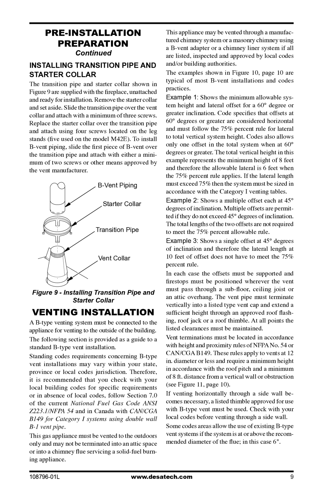
The transition pipe and starter collar shown in Figure 9 are supplied with the fireplace, unattached and ready for installation. Remove the starter collar and set aside. Slide the transition pipe over the vent collar and attach with a minimum of three screws. Replace the starter collar over the transition pipe and attach using four screws located on the leg stands (five used on the model M42E). To install
B-Vent Piping
Starter Collar
Transition Pipe
Vent Collar
Figure 9 - Installing Transition Pipe and
Starter Collar
Venting Installation
A
Standing codes requirements concerning
This gas appliance must be vented to the outdoors only and may not be terminated into an attic space or into a chimney flue servicing a
This appliance may be vented through a manufac- tured chimney system or a masonry chimney using a
The examples shown in Figure 10, page 10 are typical of most
Example 1: Shows the minimum allowable sys- tem height and lateral offset for a 60° degree or greater inclination. Code specifies that offsets at 60° degrees or greater are considered horizontal and must follow the 75% percent rule for lateral to total vertical system height. Codes also allows only one offset in the total system when at 60° degrees or greater. The total vertical height in this example represents the minimum height of 8 feet and therefore the allowable lateral is 6 feet when the 75% percent rule applies. If the lateral length must exceed 75% then the system must be sized in accordance with the Category I venting tables.
Example 2: Shows a multiple offset each at 45° degrees of inclination. Multiple offsets are permit- ted if they do not exceed 45° degrees of inclination. The total lengths of the two offsets are not required to meet the 75% percent allowable rule.
Example 3: Shows a single offset at 45° degrees of inclination and therefore the lateral length at 10 feet of offset does not have to meet the 75% percent rule.
In each case the offsets must be supported and firestops must be positioned wherever the vent must pass through a
Vent terminations must be located in accordance with height and proximity rules of NFPA No. 54 or CAN/CGA B149. These rules apply to vents at 12 in. diameter or less and require a minimum height in accordance with the roof pitch and a minimum of 8 ft. distance from a vertical wall or obstruction (see Figure 11, page 10).
If venting horizontally through a side wall be- comes necessary, a listed thimble approved for use with
Some codes areas allow the use of existing