Pre-Installation
Preparation
CLEARANCES
Minimum clearances to combustibles are:
•Back and Sides of Outer Surround. . 0" min.
•Drywall to Sides of Front Face
| (Nailing Flanges). . | . | . | . | . | . | . 0" min. |
• | “B” Vent Surfaces. . . | . | . | . | . | . | . 1" min. |
• | Ceiling to Opening. . | . | . | . | . | . | . 42" min. |
• Floor | . | . | . | . | . | . 0" min. | |
• | Perpendicular Wall. . | . | . | . | . | See Figure 6 | |
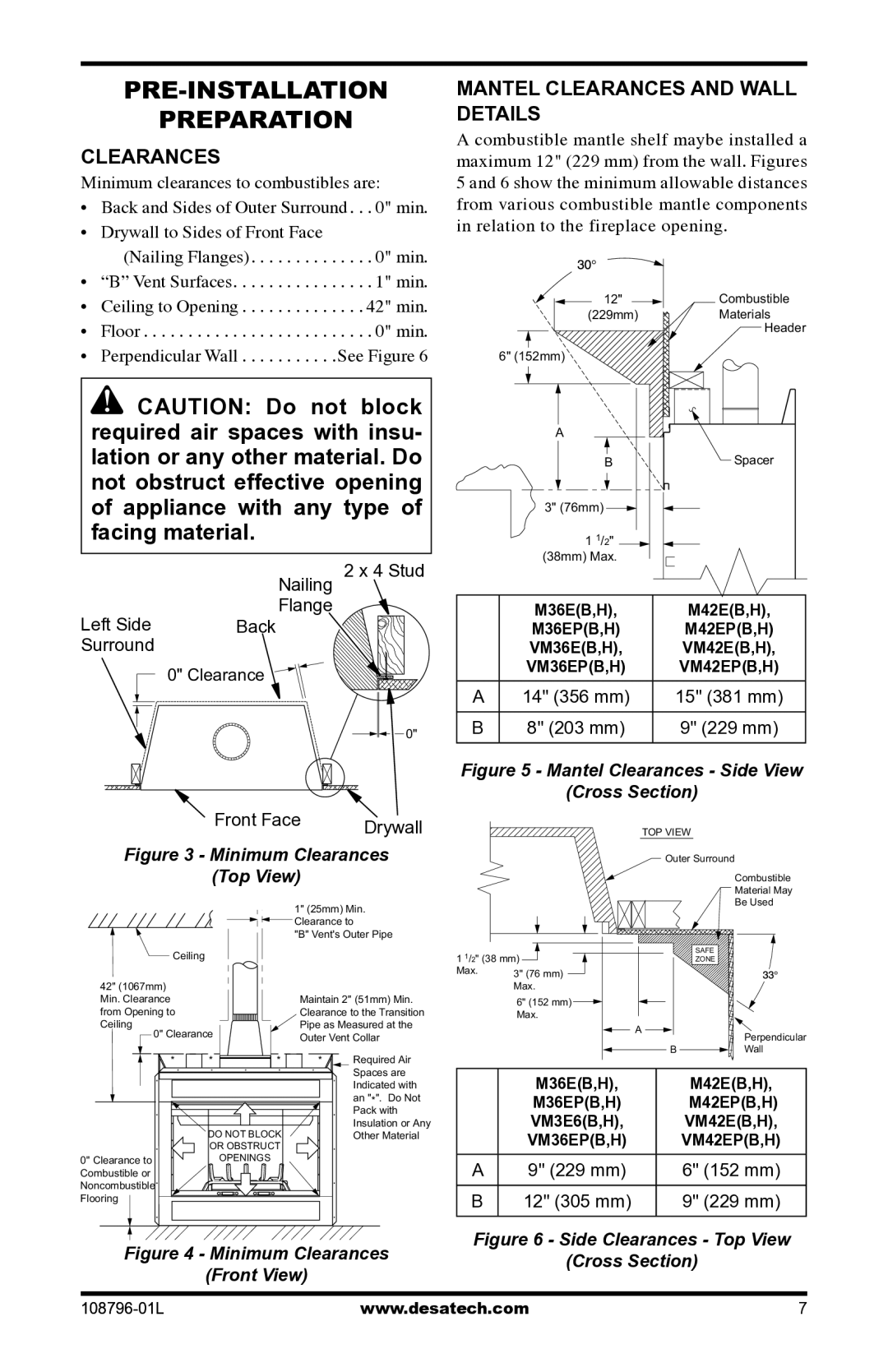
MANTEL CLEARANCES and Wall Details
A combustible mantle shelf maybe installed a maximum 12" (229 mm) from the wall. Figures 5 and 6 show the minimum allowable distances from various combustible mantle components in relation to the fireplace opening.
12" | Combustible |
(229mm) | Materials |
Header
6" (152mm)
![]() CAUTION: Do not block required air spaces with insu- lation or any other material. Do not obstruct effective opening of appliance with any type of facing material.
CAUTION: Do not block required air spaces with insu- lation or any other material. Do not obstruct effective opening of appliance with any type of facing material.
| Nailing 2 x 4 Stud | |
Left Side | Flange |
|
Back |
| |
Surround |
|
|
| 0" Clearance |
|
|
| 0" |
| Front Face | Drywall |
|
| |
Figure 3 - Minimum Clearances | ||
| (Top View) |
|
| 1" (25mm) Min. | |
| Clearance to |
|
| "B" Vent's Outer Pipe | |
| Ceiling |
|
| A |
|
| B | Spacer |
| 3" (76mm) |
|
| 1 1/2" |
|
| (38mm) Max. |
|
| M36E(B,H), | M42E(B,H), |
| M36EP(B,H) | M42EP(B,H) |
| VM36E(B,H), | VM42E(B,H), |
| VM36EP(B,H) | VM42EP(B,H) |
A | 14" (356 mm) | 15" (381 mm) |
B | 8" (203 mm) | 9" (229 mm) |
Figure 5 - Mantel Clearances - Side View | ||
| (Cross Section) | |
|
| TOP VIEW |
|
| Outer Surround |
|
| Combustible |
|
| Material May |
|
| Be Used |
1 1/2" (38 mm) | SAFE | |
ZONE | ||
Max. | 3" (76 mm) |
|
|
| |
42" (1067mm) Min. Clearance from Opening to Ceiling
0" Clearance |
| |
* | * | * |
| DO NOT BLOCK | |
| OR OBSTRUCT | |
0" Clearance to |
| OPENINGS |
Combustible or |
|
|
Noncombustible |
|
|
Flooring |
|
|
Maintain 2" (51mm) Min. Clearance to the Transition Pipe as Measured at the Outer Vent Collar
*Required Air Spaces are
Indicated with an "*". Do Not Pack with Insulation or Any Other Material
| Max. |
|
| 6" (152 mm) |
|
| Max. |
|
| A | Perpendicular |
|
| |
| B | Wall |
| M36E(B,H), | M42E(B,H), |
| M36EP(B,H) | M42EP(B,H) |
| VM3E6(B,H), | VM42E(B,H), |
| VM36EP(B,H) | VM42EP(B,H) |
A | 9" (229 mm) | 6" (152 mm) |
B | 12" (305 mm) | 9" (229 mm) |