OWNER’S MANUAL
INSTALLATION
Continued
For Built-In Installation
![]() WARNING: A licensed elec- trician must connect the wiring harness to electrical supply fol- lowing all local codes. Electri- cian must provide a clamp on the box cover to secure the wir- ing. Wiring should be routed through the bushing in the hole on the outer casing of heater.
WARNING: A licensed elec- trician must connect the wiring harness to electrical supply fol- lowing all local codes. Electri- cian must provide a clamp on the box cover to secure the wir- ing. Wiring should be routed through the bushing in the hole on the outer casing of heater.
Follow instructions Removing Valve Cover Shield (page 11), then
1. | Install a snap bushing found in hardware |
| kit into one of the holes found on rear of |
| valve cover shield. The other hole is for |
| a strain relief clamp (not supplied) to |
| secure incoming electrical supply. |
2. | Follow steps 2 through 6 in Installing |
| Blower Assembly, pages 11 and 12. |
| Also remove black wire from middle |
| switch terminal 2. |
3. | Remove black plastic strain relief and |
| power cord from switch plate. The |
| power cord supplied will not be used in |
|
Fan Switch
(Auto/Off/On)
1Auto
| Off | 2 |
|
|
|
|
|
|
|
|
|
|
| 3 | Blue |
| Thermostat | ||||||
|
|
| On |
|
|
| Switch | ||||
|
|
|
|
|
| (N.O.) | |||||
110/115 |
|
| Red |
|
|
|
| Blue | |||
V.A.C. |
|
|
|
| Blower | ||||||
| Black |
|
|
|
|
|
|
|
| Motor | |
|
|
|
|
|
|
|
|
| |||
|
|
|
|
|
|
| Red |
| |||
| White |
|
|
|
|
|
| White |
| ||
| Green |
|
|
|
|
|
| Green | |||
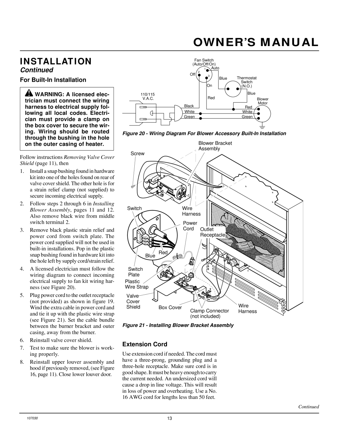
Figure 20 - Wiring Diagram For Blower Accessory Built-In Installation
Blower Bracket
Assembly
Screw
Switch | Wire |
| Harness |
| Power |
| Cord Outlet |
3 | Receptacle |
2 |
|
1 |
|
snap bushing found in hardware kit into |
the hole left by supply cord/strain relief. |
4. A licensed electrician must follow the |
wiring diagram to connect incoming |
electrical supply to fan kit wiring har- |
ness (see Figure 20). |
Blue
Switch
Plate
Plastic
Wire Strap
Red
5. | Plug power cord to the outlet receptacle |
| (not provided) as shown in figure 19. |
| Wind the extra cable in power cord and |
| and tie it up with the plastic wire strap |
| (see Figure 21). Set the cable bundle |
| between the burner bracket and outer |
| casing, away from the burner. |
6. | Reinstall valve cover shield. |
7. | Test to make sure the blower is work- |
| ing properly. |
8. | Reinstall upper louver assembly and |
| hood if previously removed, (see Figure |
| 16, page 11). Close lower louver door. |
Valve |
|
|
Cover |
| Wire |
Shield | Box Cover | |
| Clamp Connector | Harness |
| (not included) |
|
Figure 21 - Installing Blower Bracket Assembly
Extension Cord
Use extension cord if needed. The cord must have a
Continued
107030 | 13 |