Fireplace
Installation
Continued
11.Peel off backing paper and stick supplied wiring diagram decal on firebox bottom ap- proximately 12" in front of blower (see Figure 27, page 19).
Blower Wiring Diagram
![]() CAUTION: Label all wires prior to disconnection when servicing controls. Wiring errors can cause improper and dan- gerous operation. Verify proper operation after servicing.
CAUTION: Label all wires prior to disconnection when servicing controls. Wiring errors can cause improper and dan- gerous operation. Verify proper operation after servicing.
|
|
| Variable | Fan Switch | |
|
| Fan Switch | |||
|
|
|
| (N.O.) | |
|
| Off | 1 | Black | |
|
|
| 2 | ||
110/115 | On |
| Blue | ||
|
| ||||
| V.A.C. Black |
| Blower | ||
|
|
|
| ||
|
| White |
| Motor | |
Green
Figure 29 - Blower Wiring Diagram for
Thermostat-Controlled Models
Installing Gas Piping to Fireplace Location
![]() WARNING: A qualified service person must connect fireplace to gas supply. Follow all local codes.
WARNING: A qualified service person must connect fireplace to gas supply. Follow all local codes.
![]() CAUTION: For propane/LP units, never connect fireplace directly to the propane/LP supply. This heater requires an external regulator (not supplied). Install theexternalregulatorbetweenthe fireplace and propane/LP supply.
CAUTION: For propane/LP units, never connect fireplace directly to the propane/LP supply. This heater requires an external regulator (not supplied). Install theexternalregulatorbetweenthe fireplace and propane/LP supply.
![]() WARNING: For natural gas, never connect heater to private
WARNING: For natural gas, never connect heater to private
Installation Items Needed
Before installing fireplace, make sure you have the items listed below.
• external regulator (supplied by installer)
• piping (check local codes)
• sealant (resistant to propane/LP gas)
• equipment shutoff valve *
• test gauge connection *
• sediment trap
• tee joint
• pipe wrench
• approved flexible gas line with gas connector (if allowed by local codes)
*A CSA
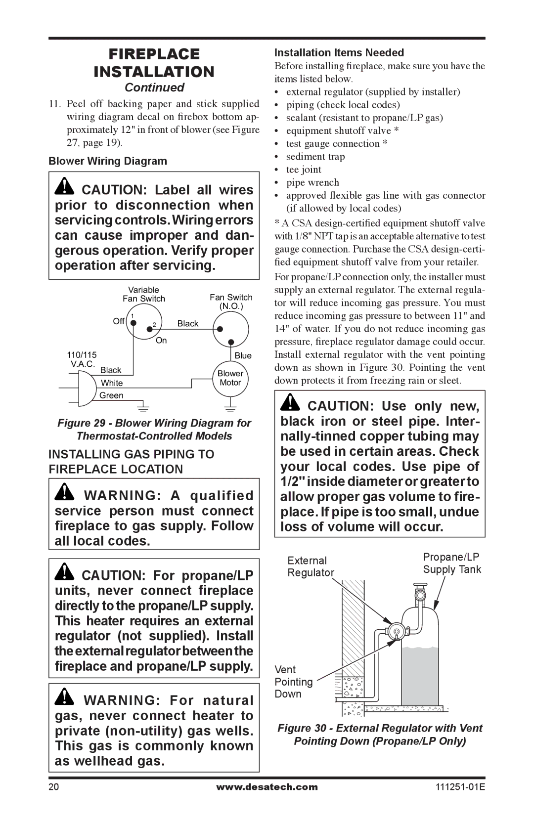
For propane/LP connection only, the installer must supply an external regulator. The external regula- tor will reduce incoming gas pressure. You must reduce incoming gas pressure to between 11" and 14" of water. If you do not reduce incoming gas pressure, fireplace regulator damage could occur. Install external regulator with the vent pointing down as shown in Figure 30. Pointing the vent down protects it from freezing rain or sleet.
![]() CAUTION: Use only new, black iron or steel pipe. Inter-
CAUTION: Use only new, black iron or steel pipe. Inter-
External | Propane/LP | |
Supply Tank | ||
Regulator | ||
|
Vent
Pointing
Down
Figure 30 - External Regulator with Vent
Pointing Down (Propane/LP Only)
20 | www.desatech.com |