Venting Installation

instructions

Continued

installation for vertical termination

Note: Vertical restrictor must be installed in all vertical installations.

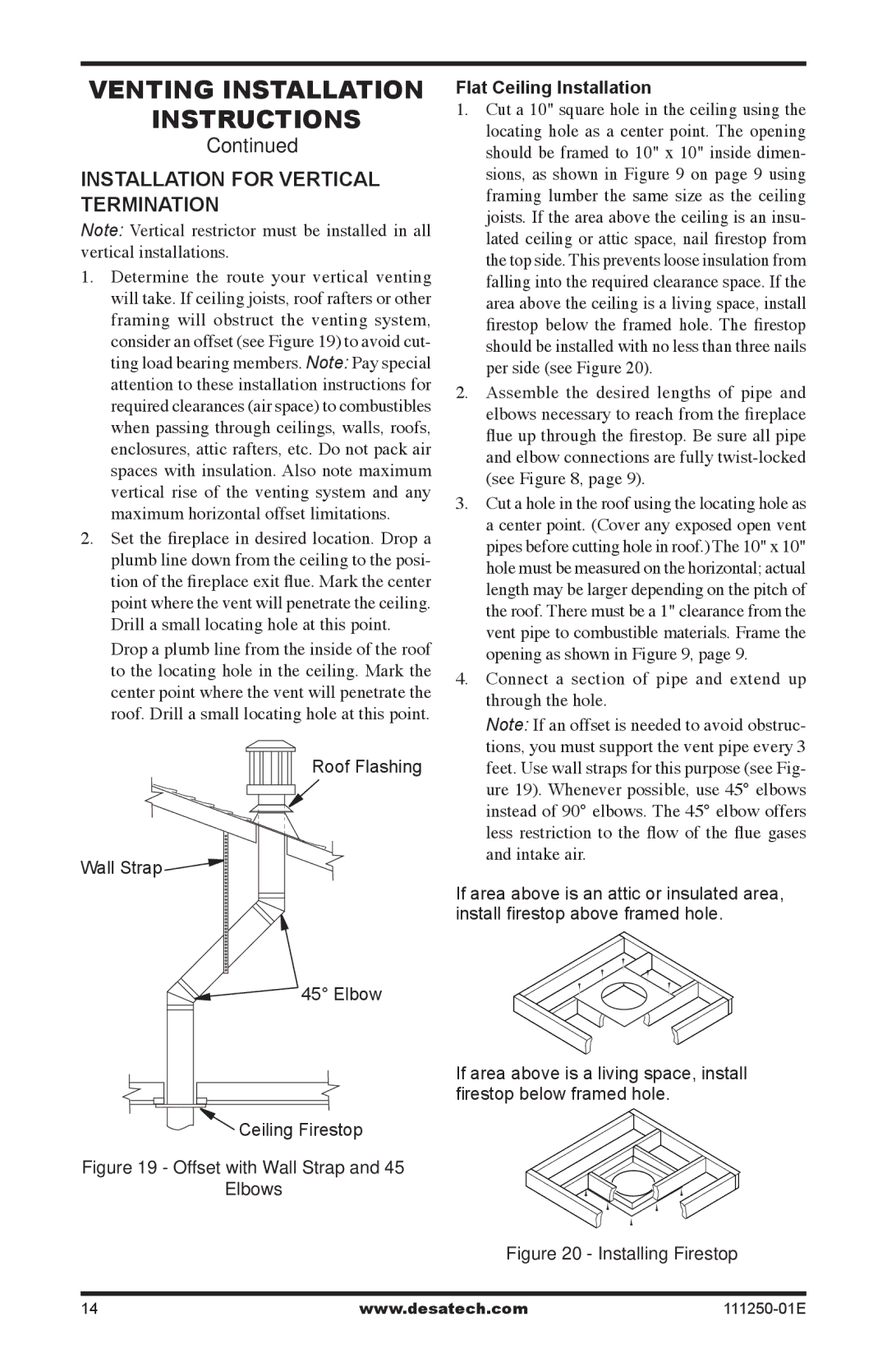
1.Determine the route your vertical venting will take. If ceiling joists, roof rafters or other framing will obstruct the venting system, consider an offset (see Figure 19) to avoid cut- ting load bearing members. Note: Pay special attention to these installation instructions for required clearances (air space) to combustibles when passing through ceilings, walls, roofs, enclosures, attic rafters, etc. Do not pack air spaces with insulation. Also note maximum vertical rise of the venting system and any maximum horizontal offset limitations.

2.Set the fireplace in desired location. Drop a plumb line down from the ceiling to the posi- tion of the fireplace exit flue. Mark the center point where the vent will penetrate the ceiling. Drill a small locating hole at this point.

Drop a plumb line from the inside of the roof to the locating hole in the ceiling. Mark the center point where the vent will penetrate the roof. Drill a small locating hole at this point.

Roof Flashing

Wall Strap

45° Elbow

Ceiling Firestop

Figure 19 - Offset with Wall Strap and 45°

Elbows

Flat Ceiling Installation

1. Cut a 10" square hole in the ceiling using the locating hole as a center point. The opening should be framed to 10" x 10" inside dimen- sions, as shown in Figure 9 on page 9 using framing lumber the same size as the ceiling joists. If the area above the ceiling is an insu- lated ceiling or attic space, nail firestop from the top side. This prevents loose insulation from falling into the required clearance space. If the area above the ceiling is a living space, install firestop below the framed hole. The firestop should be installed with no less than three nails per side (see Figure 20).

2. Assemble the desired lengths of pipe and elbows necessary to reach from the fireplace flue up through the firestop. Be sure all pipe and elbow connections are fully twist-locked (see Figure 8, page 9).

3. Cut a hole in the roof using the locating hole as a center point. (Cover any exposed open vent pipes before cutting hole in roof.) The 10" x 10" hole must be measured on the horizontal; actual length may be larger depending on the pitch of the roof. There must be a 1" clearance from the vent pipe to combustible materials. Frame the opening as shown in Figure 9, page 9.

4. Connect a section of pipe and extend up through the hole.

Note: If an offset is needed to avoid obstruc- tions, you must support the vent pipe every 3 feet. Use wall straps for this purpose (see Fig- ure 19). Whenever possible, use 45° elbows instead of 90° elbows. The 45° elbow offers less restriction to the flow of the flue gases and intake air.

If area above is an attic or insulated area, install firestop above framed hole.

If area above is a living space, install firestop below framed hole.

Figure 20 - Installing Firestop

14

www.desatech.com

111250-01E

Page 14
Image 14
Desa (V)T36NA installation manual Installation for vertical termination, Flat Ceiling Installation

(V)T36NA specifications

Desa (V)T36NA is an advanced piece of machinery designed primarily for heavy-duty applications in various industrial sectors. Known for its reliability and efficiency, this model has gained popularity among operators seeking high performance without compromising on durability.

One of the standout features of the Desa (V)T36NA is its powerful engine. It is equipped with a state-of-the-art internal combustion engine that provides robust torque and horsepower, enabling it to tackle demanding tasks with ease. This power is complemented by a highly efficient fuel system that minimizes consumption, making it both cost-effective and environmentally friendly.

The Desa (V)T36NA incorporates cutting-edge technologies that enhance its operational capabilities. Its intelligent control system allows for seamless adjustments to power settings based on task requirements. This feature not only improves performance but also extends the lifespan of the machinery by preventing overexertion. Additionally, the unit is integrated with advanced diagnostic tools that monitor performance metrics, enabling operators to identify issues before they escalate.

Another notable characteristic of the Desa (V)T36NA is its robust construction. Built from high-grade materials, this machinery is designed to withstand the rigors of tough industrial environments. The frame is reinforced to handle heavy loads and resist wear and tear, which significantly reduces maintenance costs over time.

In terms of ergonomics, the machinery is designed with user comfort in mind. The operator's cabin is spacious, providing ample room and visibility for enhanced maneuverability. The controls are intuitively laid out, ensuring that operators can make adjustments quickly and efficiently.

The Desa (V)T36NA also emphasizes safety, featuring advanced safety mechanisms such as automatic braking systems and secure cabin enclosures. These features protect both the operator and the surrounding personnel, making it a reliable choice for any workspace.

Overall, the Desa (V)T36NA represents a significant advancement in heavy machinery, combining power, efficiency, and safety in one robust package. Its innovative technologies and solid construction make it an excellent investment for industries seeking to enhance productivity while ensuring operator comfort and safety. Whether in construction, manufacturing, or other heavy-duty applications, the Desa (V)T36NA stands out as a trustworthy ally in achieving operational goals.