6

LOCATION OF TERMINATION CAP

LOCATION OF TERMINATION CAP

D

E V

B L


C


Fixed


V


Closed


F


V


Openable


B

B

B

Openable Fixed Closed

H

V

B

I

V J XG

AM

NN


G


V


G

V K X

V


A

V TERMINATION CAP

X AIR SUPPLY INLET

G GAS METER

RESTRICTED AREA (TERMINATION PROHIBITED)

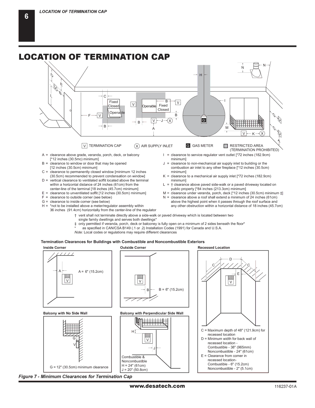
A= clearance above grade, veranda, porch, deck, or balcony [*12 inches (30.5mc) minimum]

B= clearance to window or door that may be opened [12 inches (30.5cm) minimum]

C = clearance to permanently closed window [minimum 12 inches (30.5cm) recommended to prevent condensation on window]

D = vertical clearance to ventilated soffit located above the terminal within a horizontal distance of 24 inches (61cm) from the center-line of the terminal [18 inches (45.7cm) minimum]

E= clearance to unventilated soffit [12 inches (30.5cm) minimum] F = clearance to outside corner (see below)

G = clearance to inside corner (see below)

H = *not to be installed above a meter/regulator assembly within

36 inches (91.4cm) horizontally from the center-line of the regulator

I= clearance to service regulator vent outlet [*72 inches (182.9cm) minimum]

J= clearance to non-mechanical air supply inlet to building or the combustion air inlet to any other fireplace [*12 inches (30.5cm)

minimum]

K= clearance to a mechanical air supply inlet [*72 inches (182.9cm) minimum]

L= † clearance above paved side-walk or a paved driveway located on public property [*84 inches (213.3cm) minimum]

M = clearance under veranda, porch, deck [*12 inches (30.5cm) minimum ‡]

N= clearance above a roof shall extend a minimum of 24 inches (61cm) above the highest point when it passes through the roof surface and any other obstruction within a horizontal distance of 18 inches (45.7cm)

† vent shall not terminate directly above a side-walk or paved driveway which is located between two single family dwellings and serves both dwellings*

only permitted if veranda, porch, deck or balconey is fully open on a minimum of 2 sides beneath the floor* * as specified in CAN/CSA B149 (.1 or .2) Installation Codes (1991) for Canada and U.S.A.

Note: Local codes or regulations may require different clearances

Termination Clearances for Buildings with Combustible and Noncombustible Exteriors

Inside Corner

Outside Corner

Recessed Location

AA = 6" (15.2cm)

V

Balcony with No Side Wall

G

V

G = 12" (30.5cm) minimum clearance

V

B B = 6" (15.2cm)

Balcony with Perpendicular Side Wall

H

V

J

Combustible &

Noncombustible

H = 24" (61cm)

J = 20" (50.8cm)


D

C

C

E

V

C = Maximum depth of 48" (121.9cm) for recessed location

D = Minimum width for back wall of recessed location - Combustible - 38" (965mm) Noncombustible - 24" (61cm)

E = Clearance from corner in recessed location- Combustible - 6" (15.2cm) Noncombustible - 2" (5.1cm)

Figure 7 - Minimum Clearances for Termination Cap

www.desatech.com

116237-01A

Page 6
Image 6
Desa (V)VC42PE, (V)VC42NE installation manual Location of Termination CAP, Termination CAP AIR Supply Inlet GAS Meter

(V)VC42PE, (V)VC42NE specifications

Desa (V)VC42NE and (V)VC42PE are innovative heating solutions that cater to modern residential and commercial spaces. These advanced units embody a combination of efficiency, sustainability, and user-friendly features, making them highly sought after in the market.

The (V)VC42NE model stands out for its high energy efficiency, designed to provide optimal heating performance while minimizing energy consumption. This unit incorporates state-of-the-art condensing technology, which allows it to extract additional heat from exhaust gases, enhancing its overall energy efficiency. With a commendable seasonal efficiency rating, it is suitable for environments where reduced carbon footprints are a priority.

On the other hand, the (V)VC42PE model is engineered to offer unparalleled versatility. It supports a range of fuel options, including natural gas and propane, making it adaptable to various installations. This flexibility is particularly beneficial for users who may want to switch fuel sources in the future. The (V)VC42PE also includes a powerful fan system, which ensures even heat distribution throughout the space, eliminating cold spots.

Both models are equipped with advanced safety features that comply with stringent industry standards. These include flame failure devices, pressure relief valves, and overheat protection systems that ensure the units operate safely under all conditions. Additionally, they are designed for low maintenance, with accessible components that simplify servicing and repairs.

One of the standout characteristics of both Desa models is their intuitive control systems. The units feature digital thermostats that allow users to set and monitor temperatures effortlessly. Moreover, they offer programmable settings that enable users to optimize heating schedules according to their lifestyle needs. This feature contributes to enhanced comfort while further promoting energy savings.

In terms of design, both the (V)VC42NE and (V)VC42PE models possess a sleek, modern aesthetic that integrates seamlessly into various interior styles. Their compact size allows for easy installation in tight spaces, making them an ideal choice for apartments, offices, and other limited areas.

In summary, Desa (V)VC42NE and (V)VC42PE units are exemplary heating systems that combine efficiency, safety, and user-friendly features, making them suitable for a wide range of applications. With their advanced technologies and commitment to sustainability, these models are poised to meet the demands of today's energy-conscious consumers.