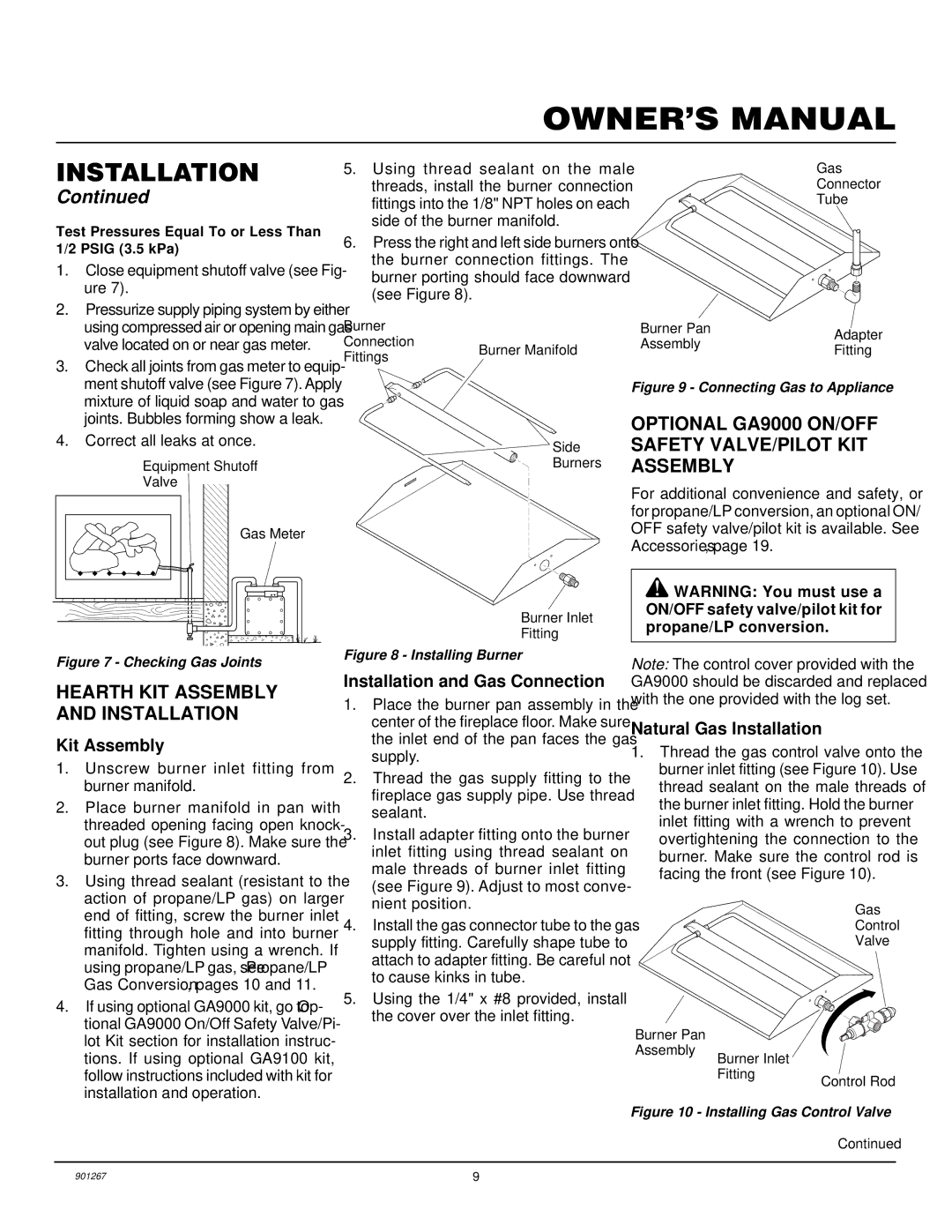
VVMR18, VVMR24 specifications
Desa VVMR18 and VVMR24 are advanced solutions designed to enhance the efficiency of commercial and industrial heating systems. These models represent a significant leap in technology within the realm of industrial heaters, emphasizing energy efficiency, reliability, and user-friendly operation.One of the main features of both the VVMR18 and VVMR24 models is their highly efficient heat exchange technology. The design incorporates a compact heat exchanger that maximizes thermal efficiency while minimizing energy waste. This means that users can not only save on operational costs but also reduce their carbon footprint, aligning with global sustainability goals.
The VVMR series utilizes advanced control systems that allow for precise temperature regulation and monitoring. These control systems are equipped with intelligent algorithms that adapt to varying load demands and external conditions, ensuring optimal performance at all times. This feature is particularly beneficial in environments where temperature fluctuations are common, providing stable heating without the need for constant manual adjustment.
In terms of construction, both models boast robust builds, designed to withstand the rigors of industrial use. The use of high-quality materials enhances durability and longevity, reducing maintenance requirements and extending the lifespan of the units. Additionally, their modular design facilitates easy installation and servicing, which is critical in industrial settings where downtime can be costly.
Safety is another critical characteristic of the VVMR18 and VVMR24 models. They come equipped with multiple safety features, including over-temperature protection and pressure relief systems, ensuring reliable operation without compromising on safety. These features are essential in industrial environments where safety regulations are paramount.
In conclusion, the Desa VVMR18 and VVMR24 offer a blend of efficiency, advanced technology, and robust design. Their intelligent control systems, efficient heat exchange technology, and focus on safety make them ideal choices for businesses seeking reliable heating solutions. Investing in these models not only supports operational efficiency but also promotes a commitment to environmental responsibility, making them a wise choice for modern industrial applications.

