ENG LI S H
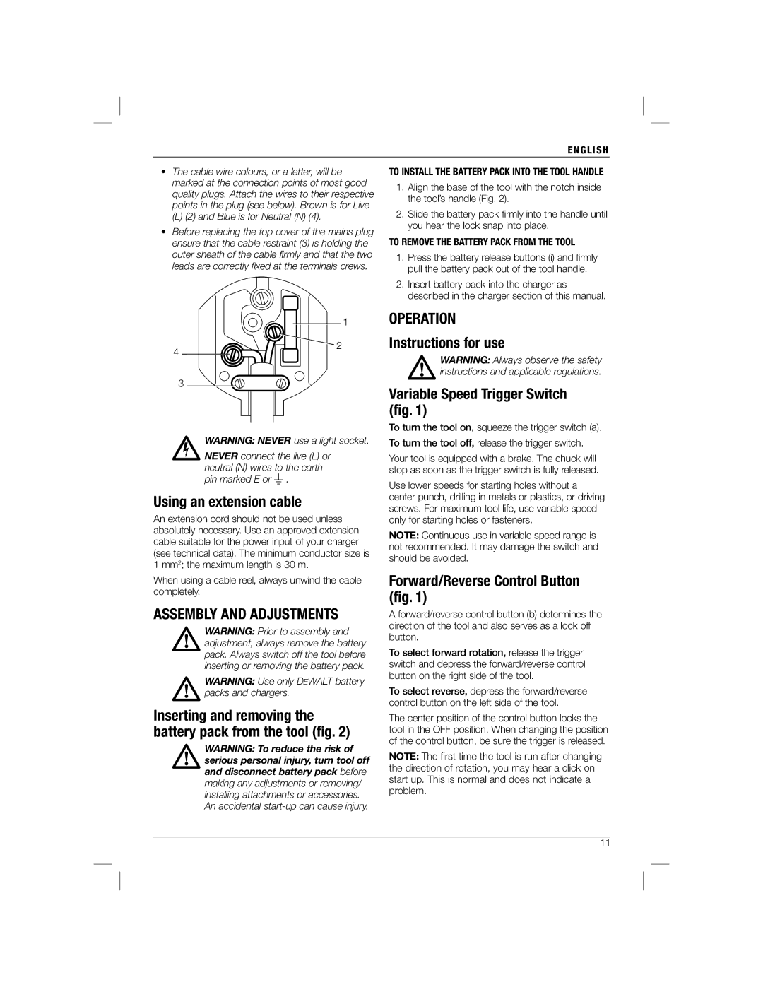
•The cable wire colours, or a letter, will be marked at the connection points of most good quality plugs. Attach the wires to their respective points in the plug (see below). Brown is for Live
(L)(2) and Blue is for Neutral (N) (4).
•Before replacing the top cover of the mains plug ensure that the cable restraint (3) is holding the outer sheath of the cable firmly and that the two leads are correctly fixed at the terminals crews.
TO INSTALL THE BATTERY PACK INTO THE TOOL HANDLE
1.Align the base of the tool with the notch inside the tool’s handle (Fig. 2).
2.Slide the battery pack firmly into the handle until you hear the lock snap into place.
TO REMOVE THE BATTERY PACK FROM THE TOOL
1.Press the battery release buttons (i) and firmly pull the battery pack out of the tool handle.
2.Insert battery pack into the charger as described in the charger section of this manual.
4
1
2
OPERATION
Instructions for use
WARNING: Always observe the safety instructions and applicable regulations.
3
WARNING: NEVER use a light socket.
NEVER connect the live (L) or neutral (N) wires to the earth pin marked E or ![]() .
.
Using an extension cable
An extension cord should not be used unless absolutely necessary. Use an approved extension cable suitable for the power input of your charger (see technical data). The minimum conductor size is 1 mm2; the maximum length is 30 m.
When using a cable reel, always unwind the cable completely.
ASSEMBLY AND ADJUSTMENTS
WARNING: Prior to assembly and adjustment, always remove the battery pack. Always switch off the tool before inserting or removing the battery pack.
WARNING: Use only DEWALT battery packs and chargers.
Inserting and removing the battery pack from the tool (fig. 2)
WARNING: To reduce the risk of serious personal injury, turn tool off and disconnect battery pack before making any adjustments or removing/ installing attachments or accessories. An accidental
Variable Speed Trigger Switch (fig. 1)
To turn the tool on, squeeze the trigger switch (a).
To turn the tool off, release the trigger switch.
Your tool is equipped with a brake. The chuck will stop as soon as the trigger switch is fully released.
Use lower speeds for starting holes without a center punch, drilling in metals or plastics, or driving screws. For maximum tool life, use variable speed only for starting holes or fasteners.
NOTE: Continuous use in variable speed range is not recommended. It may damage the switch and should be avoided.
Forward/Reverse Control Button (fig. 1)
A forward/reverse control button (b) determines the direction of the tool and also serves as a lock off button.
To select forward rotation, release the trigger switch and depress the forward/reverse control button on the right side of the tool.
To select reverse, depress the forward/reverse control button on the left side of the tool.
The center position of the control button locks the tool in the OFF position. When changing the position of the control button, be sure the trigger is released.
NOTE: The first time the tool is run after changing the direction of rotation, you may hear a click on start up. This is normal and does not indicate a problem.
3611