THE BLADE GUARD MANUALLY UNLESS THE SAW IS TURNED OFF.
NOTE: Certain special cuts will require that you manually raise the guard. See section on cutting base molding up to
The front section of the guard is louvered for visibility while cutting. Although the louvers dramatically reduce flying debris, they are openings in the guard and safety glasses should be worn at all times when viewing through the louvers.
AUTOMATIC ELECTRIC BRAKE (120 VOLT ONLY) Your saw is equipped with an automatic electric blade brake which stops the saw blade within 5 seconds of trig- ger release. This is not adjustable.
On occasion, there may be a delay after trigger release to brake engagement. On rare occasions, the brake may not engage at all and the blade will coast to a stop.
If a delay or “skipping” occurs, turn the saw on and off 4 or 5 times. If the condition persists, have the tool serviced by an authorized DEWalt service center.
Always be sure the blade has stopped before removing it from the kerf. The brake is not a substitute for guards or for ensuring your own safety by giving the saw your complete attention.
Brushes
DISCONNECT PLUG FROM POWER SUPPLY
Inspect carbon brushes regularly by unplugging tool, removing the brush inspection cap (Figure 3) and with- drawing the brush assembly. Keep brushes clean and slid- ing freely in their guides. Always replace a used brush in the same orientation in the holder as it was prior to its removal. Carbon brushes have varying symbols stamped into their sides, and if the brush is worn down to the line closest to the spring, they must be replaced. Use only identical DEWALT brushes. Use of the correct grade of brush is essential for proper operation of electric brake. New brush assemblies are available at DEWALT service centers. The tool should be allowed to “run in” (run at no load) for 10 minutes before use to seat new brushes. The electric brake may be erratic in operation until the brushes are properly seated (worn in).
While “running in” DO NOT TIE, TAPE, OR OTHERWISE LOCK THE TRIGGER SWITCH ON. HOLD BY HAND ONLY.
Operation
Plug the saw into any household 60 Hz power source. Refer to the nameplate for voltage. Be sure the cord will not interfere with your work.
SWITCH
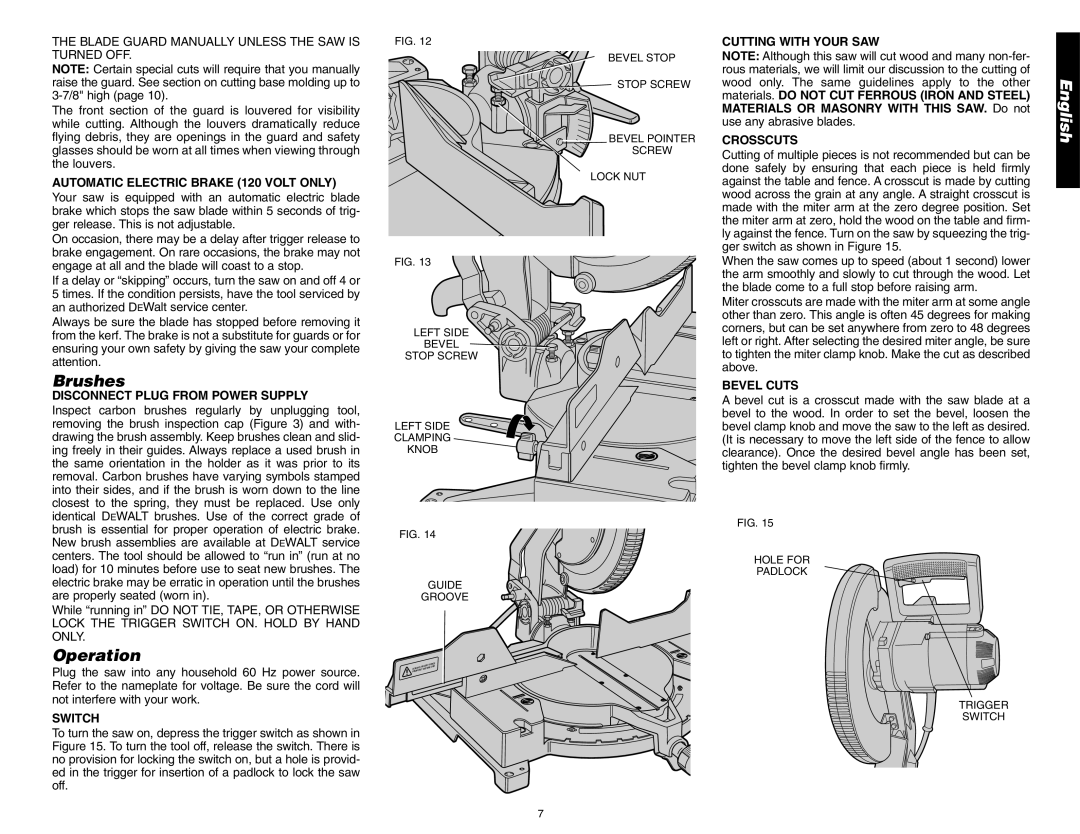
To turn the saw on, depress the trigger switch as shown in Figure 15. To turn the tool off, release the switch. There is no provision for locking the switch on, but a hole is provid- ed in the trigger for insertion of a padlock to lock the saw off.
FIG. 12
BEVEL STOP
STOP SCREW
![]() BEVEL POINTER
BEVEL POINTER
SCREW
LOCK NUT
FIG. 13
LEFT SIDE
BEVEL
STOP SCREW
LEFT SIDE
CLAMPING
KNOB
FIG. 14
GUIDE
GROOVE
ER
NG
DA
ADJUST | FENCE | |
| USE | |
ALWAYSLY BEFORE |
| |
PROPER |
|
|
DANGERAY
KEEPMABWLADE
FRO
CUTTING WITH YOUR SAW
NOTE: Although this saw will cut wood and many
CROSSCUTS
Cutting of multiple pieces is not recommended but can be done safely by ensuring that each piece is held firmly against the table and fence. A crosscut is made by cutting wood across the grain at any angle. A straight crosscut is made with the miter arm at the zero degree position. Set the miter arm at zero, hold the wood on the table and firm- ly against the fence. Turn on the saw by squeezing the trig- ger switch as shown in Figure 15.
When the saw comes up to speed (about 1 second) lower the arm smoothly and slowly to cut through the wood. Let the blade come to a full stop before raising arm.
Miter crosscuts are made with the miter arm at some angle other than zero. This angle is often 45 degrees for making corners, but can be set anywhere from zero to 48 degrees left or right. After selecting the desired miter angle, be sure to tighten the miter clamp knob. Make the cut as described above.
BEVEL CUTS
A bevel cut is a crosscut made with the saw blade at a bevel to the wood. In order to set the bevel, loosen the bevel clamp knob and move the saw to the left as desired. (It is necessary to move the left side of the fence to allow clearance). Once the desired bevel angle has been set, tighten the bevel clamp knob firmly.
FIG. 15
HOLE FOR
PADLOCK
TRIGGER
SWITCH
English
7