
DWE4557 specifications
The DeWalt DWE4557 is a powerful and robust angle grinder designed to deliver high performance and durability for both professional and DIY enthusiasts. This tool is equipped with a 4.5-inch diameter wheel and is renowned for its efficient performance in heavy-duty applications. One of its key features includes a 13-amp motor that provides a remarkable power output of 2,000 watts, ensuring that it can handle tough materials such as metal and masonry with ease.One of the standout technologies in the DWE4557 is its electronic kickback brake, which engages in the event of a wheel bind-up. This feature helps to minimize the risk of injury and maximizes user safety by bringing the wheel to a stop quickly. The grinder also boasts a no-volt release switch that prevents the tool from starting unexpectedly when reconnected to a power source—a vital safety consideration for frequent users.
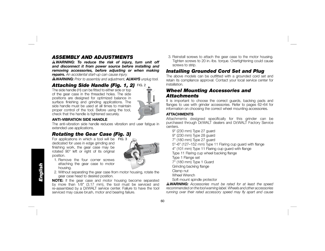
The DWE4557 is designed with user comfort in mind. It has an anti-vibration handle that significantly reduces the amount of vibration felt during operation, allowing for prolonged use without causing discomfort to the user’s hands and arms. The handle can be adjusted for optimal control and comfort, accommodating different user preferences.
Additionally, the angle grinder has an integrated safety guard that can be easily adjusted for convenience and operational versatility. The guard protects the user from debris and sparks while grinding or cutting, thereby enhancing safety during use. The DWE4557 also features a spindle lock for easy wheel changes, making it quick and straightforward to switch between different attachments based on the job at hand.
It is worth noting that the DeWalt DWE4557 is designed for durability. It includes a robust, durable construction that can withstand the rigors of heavy usage, ensuring a long lifespan of the tool. The gear case is also designed for longevity, with a high-performance drive system that ensures consistent and reliable operation.
Overall, the DeWalt DWE4557 is a reliable angle grinder that combines power, performance, and safety features in a compact and durable design. Whether for professional applications or personal projects, this tool is well-equipped to deliver outstanding results in a variety of grinding and cutting tasks.