915GM-MIGF specifications
The DFI 915GM-MIGF is a compact yet powerful Mini ITX motherboard designed for use in a diverse range of applications, from industrial control systems to compact home theater PCs. This board is built around the Intel 915GM chipset and is compatible with Intel's Pentium 4 processors, including the high-performance Pentium 4 HT (Hyper-Threading) models. This compatibility ensures that users can leverage both exceptional computing power and reliable performance for various tasks.One of the standout features of the DFI 915GM-MIGF is its support for dual-channel DDR2 memory, which allows for enhanced data throughput and improved system responsiveness. The motherboard supports up to 4GB of RAM, which is essential for running memory-intensive applications smoothly. This feature makes it an ideal choice for users needing robust multitasking capabilities.
The DFI 915GM-MIGF also boasts an integrated Intel GMA 900 graphics solution, which provides decent graphical performance for everyday tasks such as video playback and casual gaming. While hardcore gamers may opt for dedicated graphics cards, the integrated solution is sufficient for most users, especially in a compact form factor where space is at a premium.
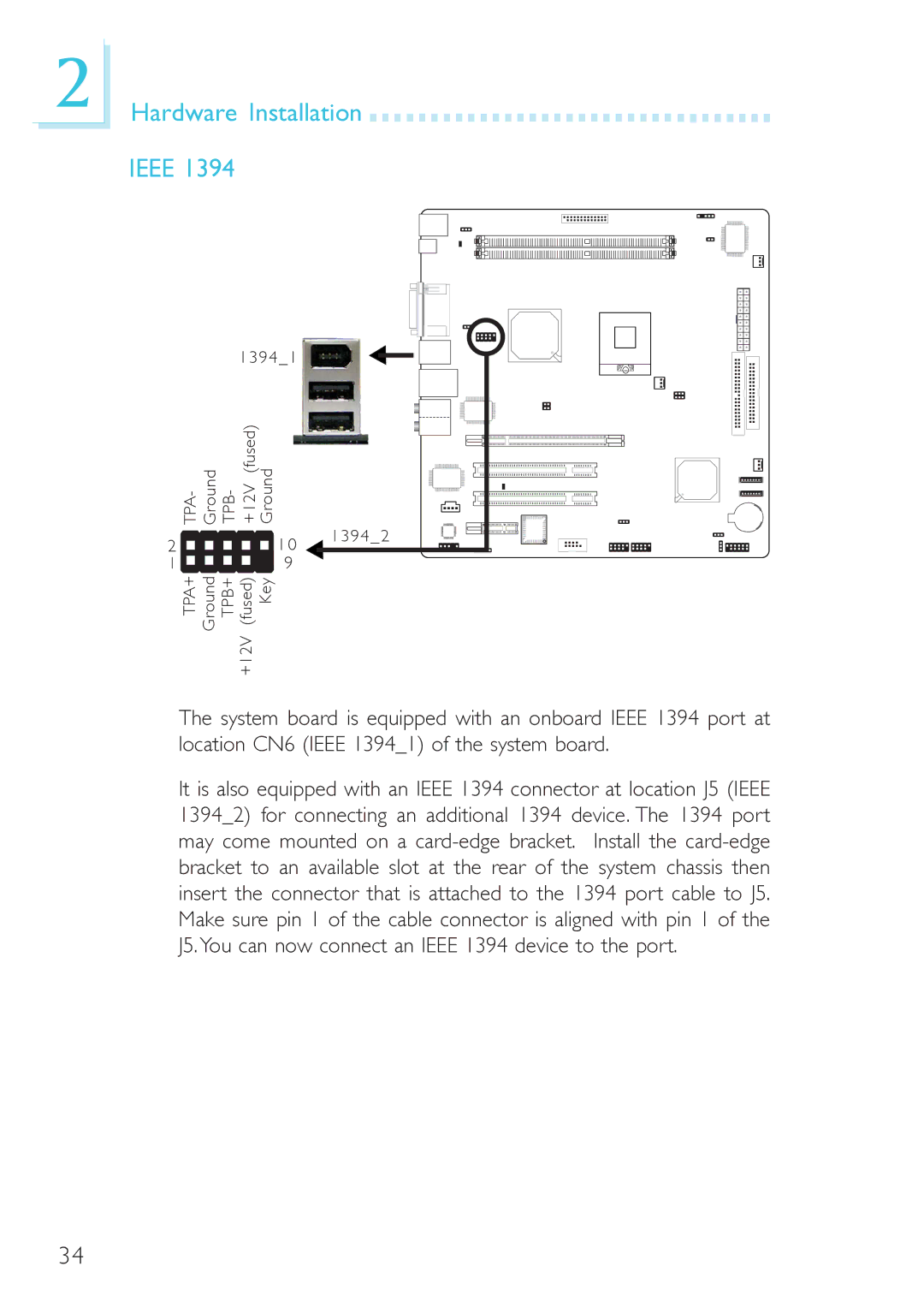
Connectivity is another strong suit of the DFI 915GM-MIGF. The motherboard is equipped with a variety of ports, including several USB 2.0 ports for connecting external devices, SATA interfaces for modern storage solutions, and an Ethernet port for reliable network connectivity. Additionally, the onboard audio codec delivers high-quality sound, making it suitable for multimedia applications.
In terms of reliability, the DFI 915GM-MIGF is designed with high-quality capacitors and components that enhance durability and stable operation, particularly in demanding environments. The board’s compact layout follows the Mini ITX standard, making it a great fit for small form-factor cases while maintaining optimal thermal efficiency.
Furthermore, the BIOS on the DFI 915GM-MIGF is user-friendly and offers various options for system tuning and configuration. This flexibility allows users to tailor their setups according to specific needs, whether for performance, stability, or energy efficiency.
In conclusion, the DFI 915GM-MIGF motherboard is an excellent choice for users needing a reliable, compact solution for various computing demands. With its solid performance, ample connectivity options, and enhanced memory support, it stands out as a versatile motherboard in today’s technology landscape.

