MPS 409 Setup Guide
This guide provides basic instructions for an experienced technician to install, set up, and operate the Extron® Media Presentation Switcher, MPS 409. Where possible in the following pages, line drawings are used to clarify steps discussed in the text. Installation and service must be performed by authorized personnel only.
Installation
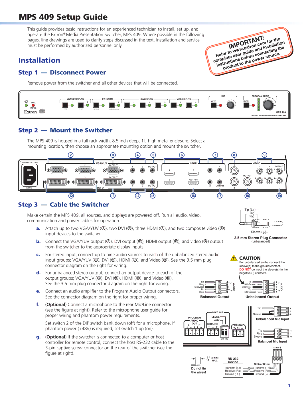
Step 1 — Disconnect Power
Remove power from the switcher and all other devices that will be connected.
|
|
|
|
|
|
|
|
|
| MIC | PROGRAM AUDIO | |
| VGA/YUV INPUTS | DVI INPUTS |
| HDMI INPUTS |
| VIDEO INPUTS |
| MUTE | MUTE | |||
EXEC | 1 | 2 | 1 | 2 | 1 | 2 | 3 | 1 | 2 | |||
|
| |||||||||||
MODE | MODE | SINGLE |
|
|
|
|
|
|
|
|
| |
CONFIG | SEPARATE | COMBINE DVI/HDMI |
|
|
|
|
|
|
| |||
MPS 409
DIGITAL MEDIA PRESENTATION SWITCHER
Step 2 — Mount the Switcher
The MPS 409 is housed in a full rack width, 8.5 inch deep, 1U high metal enclosure. Select a mounting location, then choose an appropriate mounting option and mount the switcher.
![]()
50/60 Hz
b
12
12
l
c
VGA/YUV OUTPUT
OUTPUT
m
| d | e | f |
| g |
|
|
|
| HDMI |
|
1 | 2 | OUTPUT |
| 1 | 3 |
|
|
| 1 | 3 |
|
|
|
| 2 | OUTPUT |
|
1 | 2 | OUTPUT |
| 2 | OUTPUT |
| n | o |
| p | q |
h |
| i |
| |
1 | VIDEO |
|
| |
1 | 2 | OUTPUT | ||
| ||||
| L | L | L | |
| OUTPUT |
|
| |
| R | R | R | |
2 |
|
|
| |
| r |
| s |
Step 3 — Cable the Switcher
Make certain the MPS 409, all sources, and displays are powered off. Run all audio, video, communication and power cables for operation.
a.Attach up to two VGA/YUV (b), two DVI (l), three HDMI (f), and two composite video (h) input devices to the switcher.
b.Connect the VGA/YUV output (c), DVI output (m), HDMI output (p), and video (r) output from the switcher to the appropriate display inputs.
Tip (L+)
Ring
(R+)
![]() Sleeve (
Sleeve ( ![]() )
)
3.5mm Stereo Plug Connector
(unbalanced)
c.For stereo input, connect up to nine audio sources to each of the unbalanced stereo audio input groups; VGA/YUV (d), DVI (n), HDMI (g), and Video (i). See the 3.5 mm plug connector diagram on the right for wiring.
d.For unbalanced stereo output, connect an output device to each of the
output groups; VGA/YUV (e), DVI (o), HDMI (q), and Video (s).
See the 3.5 mm plug connector diagram on the right for wiring. | Tip |
Ring | |
| Sleeve(s) |
e. Connect an audio amplifier to the Program Audio Output connectors. | Tip |
Ring | |
See the connector diagram on the right for proper wiring. | Balanced Output |
![]() CAUTION
CAUTION
For unbalanced audio, connect the sleeve(s) to the ground contact.
DO NOT connect the sleeve(s) to the negative
AUDIO L R | Tip |
NO Ground Here | |
AUDIO L R | |
| Sleeve(s) |
Tip
NO Ground Here
Unbalanced Output
f.(Optional) Connect a microphone to the rear Mic/Line connector (see the figure at right). Refer to the microphone user guide for proper wiring and phantom power requirements.
Set switch 2 of the DIP switch bank down (off) for a microphone. If phantom power (+48V) is required, set switch 1 up (on).
g.(Optional) If the switcher is connected to a computer or host controller for remote control, connect the host
PROGRAM
AUDIO
L OUT R
MIC/LINE
LEVEL +48V
MIC/LINE ON LINE
ON |
|
1 | 2 |
OFF MIC
Tx Rx
Tip
Sleeve
Unbalanced Mic Input
Tip
Ring
Sleeve
Balanced Mic Input
Tx Rx ![]()
| (5 mm) |
| |
| MAX. |
| |
| Device |
| |
|
| Bidirectional | |
|
|
| |
Do not tin |
| Transmit (Tx) | Transmit (Tx) |
the wires! |
| Receive (Rx) | Receive (Rx) |
| Ground ( _ ) | Ground ( _ ) | |
|
|
1