MPS 409 Setup Guide (Continued)
Setup and Operation — Video Switching
The MPS switcher can be connected to as many as nine input devices simultaneously and operate in one of four switching modes: single (the default), separate, single combined, or separate combined. To view the current mode, press and hold the Mode button (VGA/YUV input #1). The associated mode LEDs (single, separate, single+combined, or separate+combined) will light.
Single Switcher Mode
Single switcher mode emulates one switcher with 9 inputs (9x1). Only one input can be selected at a time, indicated by a single lit LED on the front panel input selections. The selected video input will output on the associated group output only while the audio is output on the group output and Program Audio Output.
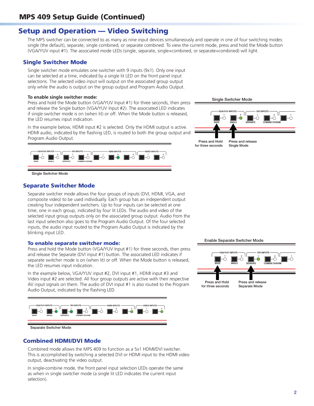
To enable single switcher mode:
Press and hold the Mode button (VGA/YUV Input #1) for three seconds, then press and release the Single button (VGA/YUV Input #2). The associated LED indicates if single switcher mode is on (when lit) or off. When the Mode button is released, the LED resumes input indication.
Single Switcher Mode
VGA/YUV INPUTS | DVI INPUTS |
| ||
1 | 2 | 1 | 2 | 1 |
MODE | SINGLE | SEPARATE | COMBINE DVI/HDMI |
|
In the example below, HDMI input #2 is selected. Only the HDMI output is active. |
| ||||||||
HDMI audio, indicated by the flashing LED, is routed to both the group output and |
| ||||||||
Program Audio Output. |
|
|
|
|
| Press and Hold | Press and release | ||
|
|
|
|
|
|
|
| ||
|
|
|
|
|
|
|
| for three seconds | Single Mode |
VGA/YUV INPUTS | DVI INPUTS |
| HDMI INPUTS |
| VIDEO INPUTS |
|
| ||
1 | 2 | 1 | 2 | 1 | 2 | 3 | 1 | 2 |
|
MODE | SINGLE | SEPARATE | COMBINE DVI/HDMI |
|
|
|
|
|
|
Single Switcher Mode
Separate Switcher Mode
Separate switcher mode allows the four groups of inputs (DVI, HDMI, VGA, and composite video) to be used individually. Each group has an independent output creating four independent switchers. Up to four inputs can be selected at one time, one in each group, indicated by four lit LEDs. The audio and video of the selected input group outputs only on the associated group output. Audio from the last input selection also goes to the Program Audio Output. Of the four selected inputs, the audio input routed to the Program Audio Output is indicated by the blinking input LED.
To enable separate switcher mode:
Press and hold the Mode button (VGA/YUV Input #1) for three seconds, then press and release the Separate (DVI input #1) button. The associated LED indicates if separate switcher mode is on (when lit) or off. When the Mode button is released, the LED resumes input indication.
Enable Separate Switcher Mode
VGA/YUV INPUTS | DVI INPUTS |
| ||
1 | 2 | 1 | 2 | 1 |
MODE | SINGLE | SEPARATE | COMBINE DVI/HDMI |
|
In the example below, VGA/YUV input #2, DVI input #1, HDMI input #3 and Video input #2 are selected. All four group outputs are active with their respective AV input signals on them. The audio of DVI input #1 is also routed to the Program Audio Output, indicated by the flashing LED.
Press and Hold |
for three seconds |
Press and release |
Separate Mode |
VGA/YUV INPUTS | DVI INPUTS |
| HDMI INPUTS |
| VIDEO INPUTS |
| ||
1 | 2 | 1 | 2 | 1 | 2 | 3 | 1 | 2 |
MODE | SINGLE | SEPARATE | COMBINE DVI/HDMI |
|
|
|
|
|
Separate Switcher Mode
Combined HDMI/DVI Mode
Combined mode allows the MPS 409 to function as a 5x1 HDMI/DVI switcher. This is accomplished by switching a selected DVI or HDMI input to the HDMI video output, deactivating the video output.
In
2