CVP1T, CVP1 specifications
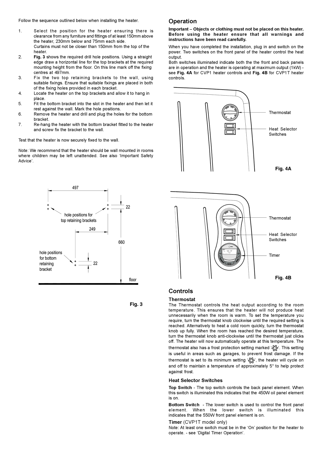
Dimplex CVP1T and CVP1 are innovative heating solutions designed to provide efficient and effective warmth for both residential and commercial spaces. These electric convector heaters are known for their stylish design, user-friendly operation, and advanced technologies that cater to modern heating needs.One of the standout features of the Dimplex CVP1T and CVP1 is their powerful heating capabilities. With a robust output, these models can quickly and effectively heat a room, making them ideal for use in various settings, including living rooms, offices, and even small commercial areas. The units are equipped with adjustable thermostats, allowing users to set their desired temperature for optimal comfort.
Both the CVP1T and CVP1 models are designed with energy efficiency in mind. They use sophisticated heating elements that provide rapid warmth while minimizing energy consumption. This allows users to enjoy a cozy environment without incurring high energy bills, which is particularly beneficial in colder climates.
In terms of technology, Dimplex incorporates advanced safety features into these heaters. The models are designed with overheat protection, ensuring that they automatically turn off if they reach an unsafe temperature. Additionally, the heaters feature tilt detection, which shuts them down if they are knocked over, providing peace of mind, especially in households with pets or young children.
The Dimplex CVP1T includes a built-in timer function, enabling users to program the heating schedule according to their lifestyle. This feature ensures that the space is warm and inviting when needed, without the need for constant manual operation. On the other hand, the CVP1 offers a more straightforward approach, focusing on essential features for those who prefer simplicity in their heating solution.
Noise levels are also a significant consideration when it comes to heating systems. The Dimplex CVP1T and CVP1 operate quietly, ensuring that they do not disrupt daily activities. This feature is particularly important for workspaces or bedrooms, where silence is often a priority.
In summary, the Dimplex CVP1T and CVP1 electric convector heaters combine advanced technologies with efficient performance. They provide adjustable heating, built-in safety features, and options for user customization, making them excellent choices for anyone looking to enhance their heating experience. With stylish designs and functional capabilities, these models stand out in the competitive heating market.

