AMPLIFIER CONTROLS
Refer to Figure 2 for details.
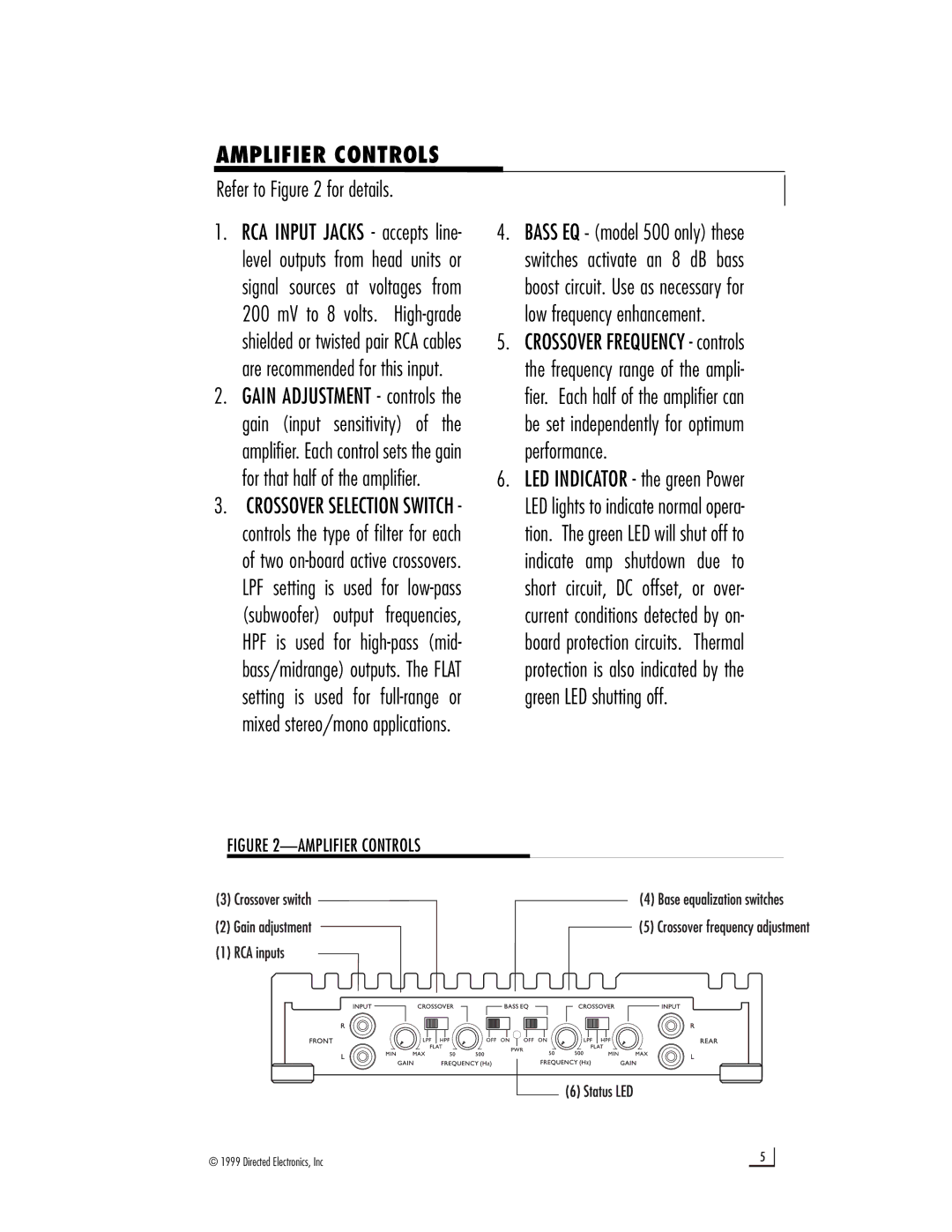
1. | RCA INPUT JACKS - accepts line- | 4. BASS EQ - (model 500 only) these | |
| level outputs from head units or | switches activate an 8 dB bass | |
| signal sources at voltages from | boost circuit. Use as necessary for | |
| 200 mV to 8 volts. | low frequency enhancement. | |
| shielded or twisted pair RCA cables | 5. CROSSOVER FREQUENCY - controls | |
| are recommended for this input. | the frequency range of the ampli- | |
2. | GAIN ADJUSTMENT - controls the | fier. Each half of the amplifier can | |
| gain (input sensitivity) of the | be set independently for optimum | |
| amplifier. Each control sets the gain | performance. | |
| for that half of the amplifier. | 6. LED INDICATOR - the green Power | |
3. | CROSSOVER SELECTION SWITCH - | LED lights to indicate normal opera- | |
| controls the type of filter for each | tion. The green LED will shut off to | |
| of two | indicate amp shutdown due to | |
| LPF setting is used for | short circuit, DC offset, or over- | |
| (subwoofer) output | frequencies, | current conditions detected by on- |
| HPF is used for | board protection circuits. Thermal | |
| bass/midrange) outputs. The FLAT | protection is also indicated by the | |
| setting is used for | green LED shutting off. | |
| mixed stereo/mono applications. |
| |
FIGURE 2—AMPLIFIER CONTROLS
© 1999 Directed Electronics, Inc | 5 |