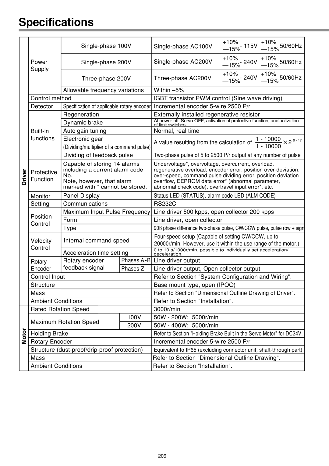
Specifications
Driver
Motor
| +10% - 115V | +10% | 50/60Hz | |||||
|
|
|
|
|
| |||
Power | +10% - 240V | +10% | 50/60Hz | |||||
Supply |
|
|
|
|
| |||
+10% - 240V | +10% | 50/60Hz | ||||||
| ||||||||
|
|
|
|
|
| |||
| Allowable frequency variations | Within |
|
|
|
| ||
|
|
|
|
| ||||
Control method |
| IGBT transistor PWM control (Sine wave driving) |
| |||||
Detector | Specification of applicable rotary encoder | Incremental encoder |
|
|
| |||
|
|
|
|
|
|
| ||
| Regeneration |
| Externally installed regenerative resistor |
|
|
| ||
|
|
|
| |||||
| Dynamic brake |
| At | |||||
|
| of limit switches |
|
|
|
| ||
Auto gain tuning |
| Normal, real time |
|
|
|
| ||
functions | Electronic gear |
| A value resulting from the calculation of 1 - 10000 | 2 0 - 17 | ||||
|
| |||||||
| (Dividing/multiplier of a command pulse) |
| 1 - 10000 |
| ||||
| Dividing of feedback pulse | |||||||
| Capable of storing 14 alarms | Undervoltage*, overvoltage, overcurrent, overload, |
|
| ||||
Protective | including a current alarm code | regenerative overload, encoder error, position | ||||||
No. |
| |||||||
Function |
| |||||||
Note, however, that alarm | overflow, EEPROM data error* (abnormal parameter, |
| ||||||
| marked with * cannot be stored. | abnormal check code), overtravel input error*, etc. |
|
| ||||
|
|
|
|
|
| |||
Monitor | Panel Display |
| Status LED (STATUS), alarm code LED (ALM CODE) |
|
| |||
Setting | Communications |
| RS232C |
|
|
|
| |
Position | Maximum Input Pulse Frequency | Line driver 500 kpps, open collector 200 kpps |
|
| ||||
|
|
|
|
|
|
| ||
Form |
| Line driver, open collector |
|
|
|
| ||
Control |
|
|
|
|
| |||
|
|
|
|
|
|
| ||
Type |
| 90ß phase difference | ||||||
|
| |||||||
Velocity | Internal command speed |
|
| |||||
20000r/min. However, use it within the use range of the motor.) | ||||||||
Control |
|
| ||||||
|
|
|
| |||||
Acceleration time setting | 0 to 10 s/1000r/min, possible to individually set acceleration/ |
| ||||||
| deceleration. |
|
|
|
| |||
Rotary | Rotary encoder | Phases A B | Line driver output |
|
|
|
| |
Encoder | feedback signal | Phases Z | Line driver output, Open collector output |
|
|
| ||
|
|
|
| |||||
Control Input |
| Refer to Section "System Configuration and Wiring". | ||||||
Structure |
|
| Base mount type, open (IPOO) |
|
|
| ||
|
|
|
| |||||
Mass |
|
| Refer to Section "Dimensional Outline Drawing of Driver". | |||||
Ambient Conditions |
| Refer to Section "Installation". |
|
|
| |||
|
|
|
|
|
|
| ||
Rated Rotation Speed |
| 3000r/min |
|
|
|
| ||
Maximum Rotation Speed | 100V | 50W - 200W: 5000r/min |
|
|
|
| ||
|
|
|
|
|
| |||
200V | 50W - 400W: 5000r/min |
|
|
|
| |||
|
|
|
|
|
| |||
|
|
| ||||||
Holding Brake |
| Refer to Section "Holding Brake Built in the Servo Motor" for DC24V. | ||||||
Rotary Encoder |
| Incremental encoder |
|
|
| |||
|
|
| ||||||
Structure | Equivalent to IP65 (excluding connector unit, | |||||||
Mass |
|
| Refer to Section "Dimensional Outline Drawing". |
| ||||
|
|
|
|
|
| |||
Ambient Conditions |
| Refer to Section "Installation". |
|
|
| |||
|
|
|
|
|
|
|
| |
206
