Communications
command | mode |
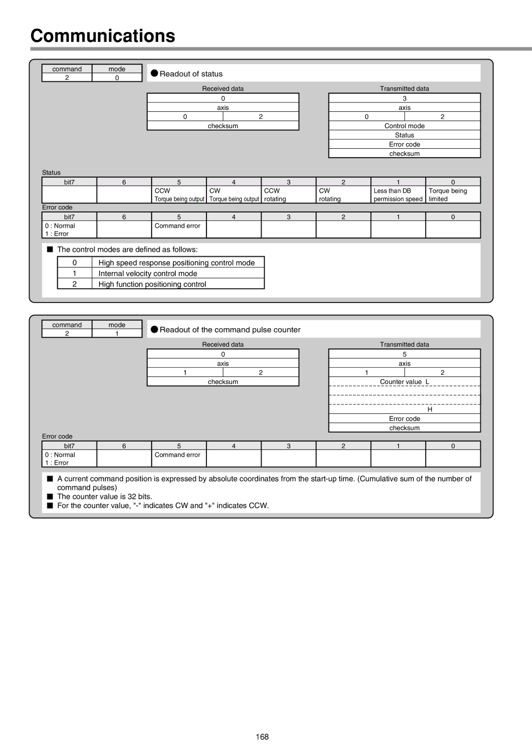
2 | 0 |
Status
![]() Readout of status
Readout of status
Received data
0
axis
0 | 2 |
checksum
Transmitted data
3
axis
0 | 2 |
Control mode
Status
Error code
checksum
| bit7 | 6 | 5 | 4 | 3 | 2 | 1 | 0 |
|
|
| CCW | CW | CCW | CW | Less than DB | Torque being |
|
|
| Torque being output | Torque being output | rotating | rotating | permission speed | limited |
Error code |
|
|
|
|
|
|
| |
| bit7 | 6 | 5 | 4 | 3 | 2 | 1 | 0 |
0 | : Normal |
| Command error |
|
|
|
|
|
1 | : Error |
|
|
|
|
|
|
|
The control modes are defined as follows:
0High speed response positioning control mode
1Internal velocity control mode
2High function positioning control
command | mode |
2 | 1 |
Error code
![]() Readout of the command pulse counter
Readout of the command pulse counter
Received data
0
axis
1 | 2 |
checksum
Transmitted data
5
axis
1 | 2 |
Counter value L
H
Error code
checksum
| bit7 | 6 | 5 | 4 | 3 | 2 | 1 | 0 |
0 | : Normal |
| Command error |
|
|
|
|
|
1 | : Error |
|
|
|
|
|
|
|
A current command position is expressed by absolute coordinates from the
The counter value is 32 bits.
For the counter value,