Allowable Load of Output Shaft
Radial Load Direction (P) | Thrust Load Directions (A, B) | ||||||||||||||||||||
|
|
| LR |
|
|
|
|
|
|
|
|
|
|
|
|
|
|
|
| ||
|
|
|
|
|
|
|
|
| A |
|
|
|
|
|
|
|
|
|
|
|
|
|
|
|
|
|
|
|
|
|
|
|
|
|
|
|
|
|
|
|
|
| |
|
|
|
|
|
|
|
|
|
|
|
|
|
|
|
|
|
|
|
|
| |
|
|
|
|
|
|
|
|
|
|
|
|
|
|
|
|
|
|
|
|
| |
|
|
|
|
|
|
|
|
| B |
|
|
|
|
|
|
| M |
|
|
|
|
|
|
|
|
|
|
|
|
|
|
|
|
|
|
|
|
|
|
|
| ||
|
|
|
|
|
|
|
|
|
|
|
|
|
|
|
|
|
|
|
| ||
|
|
|
|
|
|
|
|
|
|
|
|
|
|
|
|
|
|
|
| ||
|
|
|
|
|
|
|
|
|
|
|
|
|
|
|
|
|
|
|
|
| |
|
|
|
|
|
|
|
|
|
|
|
|
|
|
|
|
|
|
|
|
| |
|
|
|
|
|
|
|
|
|
|
|
|
|
|
|
|
|
|
|
|
| |
|
|
|
|
|
|
|
|
|
|
|
|
|
|
|
|
|
|
|
|
|
|
|
| LR/2 |
|
|
|
|
|
|
|
|
|
|
|
|
|
|
|
|
|
|
|
|
|
|
|
|
|
|
|
|
|
|
|
|
|
|
|
|
|
|
|
|
|
|
| P |
|
|
|
|
|
|
|
|
|
|
|
|
|
|
|
| |||
|
|
|
|
|
|
|
|
|
|
|
|
|
|
|
|
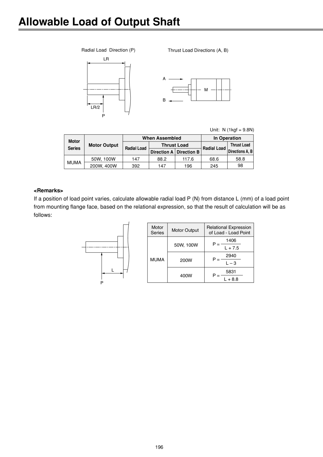
| Unit: N (1kgf = 9.8N) | ||||
|
|
|
|
|
|
|
|
|
|
|
|
| |||||||||
Motor |
|
|
|
|
|
|
| When Assembled | In Operation | ||||||||||||
| Motor Output |
| Radial Load | Thrust Load | Radial Load |
| Thrust Load | ||||||||||||||
Series |
|
|
| ||||||||||||||||||
|
|
|
|
| Direction A | Direction B | Directions A, B | ||||||||||||||
MUMA |
| 50W, 100W |
| 147 | 88.2 |
|
| 117.6 |
| 68.6 |
| 58.8 | |||||||||
| 200W, 400W |
| 392 | 147 |
|
| 196 |
| 245 |
| 98 | ||||||||||
|
|
|
|
|
|
| |||||||||||||||
<Remarks>
If a position of load point varies, calculate allowable radial load P (N) from distance L (mm) of a load point from mounting flange face, based on the relational expression, so that the result of calculation will be as follows:
L
P
Motor | Motor Output | Relational Expression | ||||
Series | of Load - Load Point | |||||
| ||||||
|
| 1406 |
|
| ||
| 50W, 100W | P = |
|
|
| |
| L + 7.5 | |||||
|
|
| ||||
|
|
|
|
|
| |
|
| 2940 |
|
| ||
MUMA | 200W | P = |
|
|
| |
L – 3 | ||||||
|
|
| ||||
|
|
|
|
|
| |
|
| 5831 |
|
| ||
| 400W | P = |
|
| ||
| L + 8.8 | |||||
|
|
| ||||
|
|
|
|
|
| |
196