Communications

 Configuration of Data Block
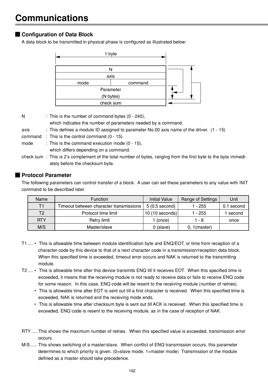
A data block to be transmitted in physical phase is configured as illustrated below:
1 byte
N
axis
mode | command |
Parameter
(N bytes)
check sum
N | : This is the number of command bytes (0 - 240), |
| which indicates the number of parameters needed by a command. |
axis | : This defines a module ID assigned to parameter No.00 axis name of the driver. (1 - 15) |
command | : This is the control command (0 - 15). |
mode | : This is the command execution mode (0 - 15), |
| which differs depending on a command. |
check sum | : This is 2’s complement of the total number of bytes, ranging from the first byte to the byte immedi- |
| ately before the checksum byte. |

 Protocol Parameter
The following parameters can control transfer of a block. A user can set these parameters to any value with INIT command to be described later.
| Name | Function | Initial Value | Range of Settings | Unit | |
|
| T1 | Timeout between character transmissions | 5 (0.5 second) | 1 - 255 | 0.1 second |
|
| T2 | Protocol time limit | 10 (10 seconds) | 1 - 255 | 1 second |
|
| RTY | Retry limit | 1 (once) | 1 - 8 | once |
|
| M/S | Master/slave | 0 (slave) | 0, 1(master) |
|
T1 .... • | This is allowable time between module identification byte and ENQ/EOT, or time from reception of a | |||||
|
| character code by this device to that of a next character code in a transmission/reception data block. | ||||
|
| When this specified time is exceeded, timeout error occurs and NAK is returned to the transmitting | ||||
|
| module. |
|
|
|
|
T2 .... • | This is allowable time after this device transmits ENQ till it receives EOT. When this specified time is | |||||
|
| exceeded, it means that the receiving module is not ready to receive data or fails to receive ENQ code | ||||
|
| for some reason. In this case, ENQ code will be resent to the receiving module (number of retries). | ||||
•This is allowable time after EOT is sent out till a first character is received. When this specified time is exceeded, NAK is returned and the receiving mode ends.
•This is allowable time after checksum byte is sent out till ACK is received. When this specified time is exceeded, ENQ code is resent to the receiving module, as in the case of reception of NAK.
RTY ..... This shows the maximum number of retries. When this specified value is exceeded, transmission error
occurs.
M/S ..... This shows switching of a master/slave. When conflict of ENQ transmission occurs, this parameter
determines to which priority is given. (0=slave mode, 1=master mode) Transmission of the module defined as a master should take precedence.
162