Communications
command | mode |
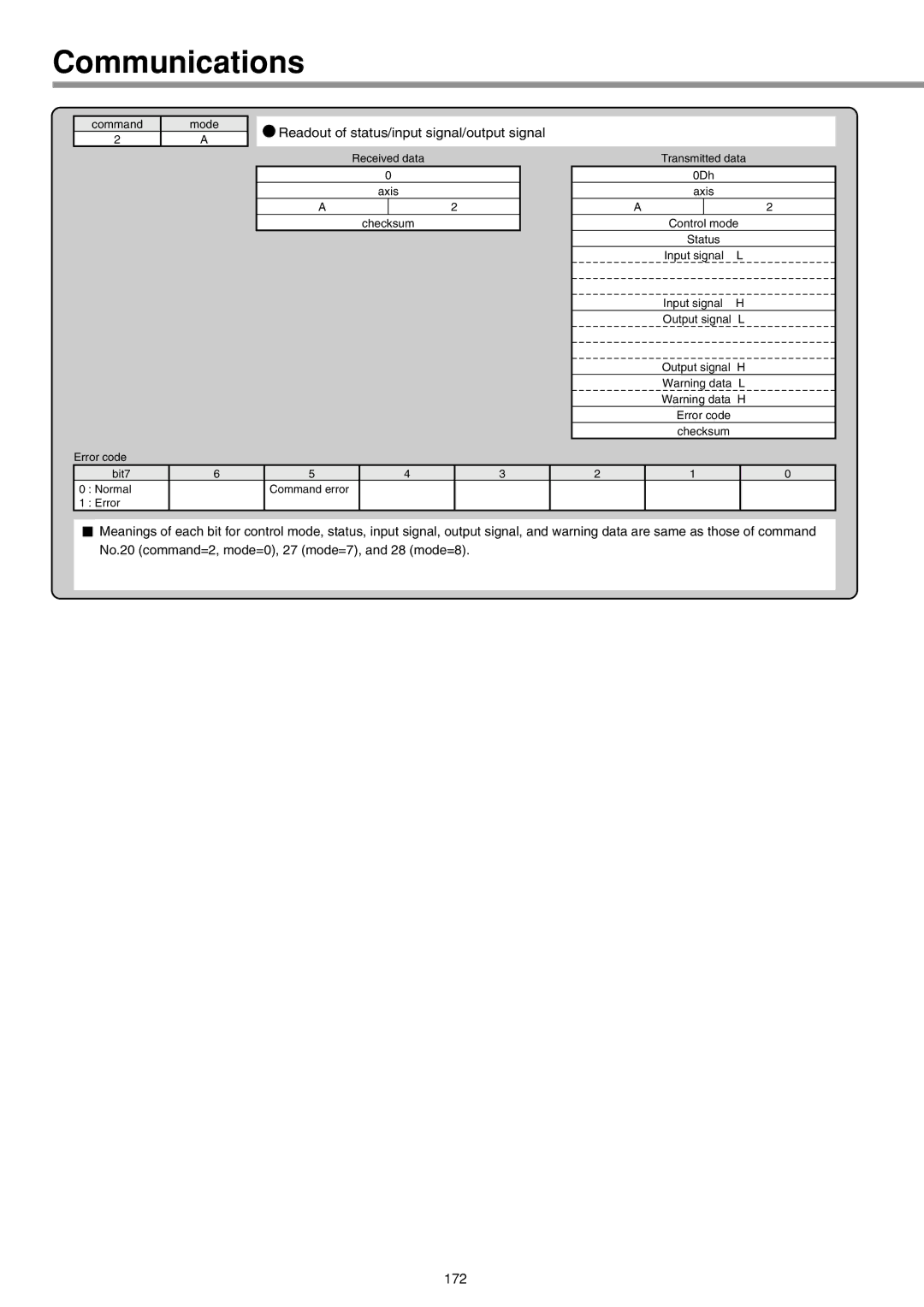
2 | A |
Error code
![]() Readout of status/input signal/output signal
Readout of status/input signal/output signal
| Received data | |
| 0 | |
| axis | |
A |
| 2 |
| checksum | |
Transmitted data
0Dh
axis
A |
| 2 |
Control mode | ||
Status |
| |
Input signal | L | |
Input signal H
Output signal L
Output signal H
Warning data L
Warning data H
Error code
checksum
| bit7 | 6 | 5 | 4 | 3 | 2 | 1 | 0 |
0 | : Normal |
| Command error |
|
|
|
|
|
1 | : Error |
|
|
|
|
|
|
|
Meanings of each bit for control mode, status, input signal, output signal, and warning data are same as those of command No.20 (command=2, mode=0), 27 (mode=7), and 28 (mode=8).