Manuals
/
Directed Electronics
/
Computer Equipment
/
Network Card
Directed Electronics
K10 door lock harness H4, wire connection guide, LED, 2-pin WHITE plug, H2/A
Models:
K10
1
7
16
16
Download
16 pages
33.97 Kb
4
5
6
7
8
9
10
11
Page 7
Image 7
Page 6
Page 8
Page 7
Image 7
Page 6
Page 8
Contents
Model K10
installation guide
power-up wiring quick reference guide
table of contents
door lock harness H4, wire connection guide
module programming system features menus feature descriptions
H1/1 ORANGE - Ground-When-Armed Output
primary harness H1 wire connection guide
primary harness H1 wiring diagram
primary harness wire descriptions
H1/3 WHITE/BLUE - Channel 3 Output
H1/2 WHITE - Parking Light Output
H1/4 BLACK/WHITE - 200 mA Domelight Supervision Output
H1/10 BROWN - Horn Honk Output
H1/6 BLUE - 200 mA Second Unlock Output
H1/8 BLACK - Chassis Ground Connection
H1/9 YELLOW + Ignition Input
H1/12 RED/WHITE channel 2, 200mA - output
H1/11 RED +12V constant power input
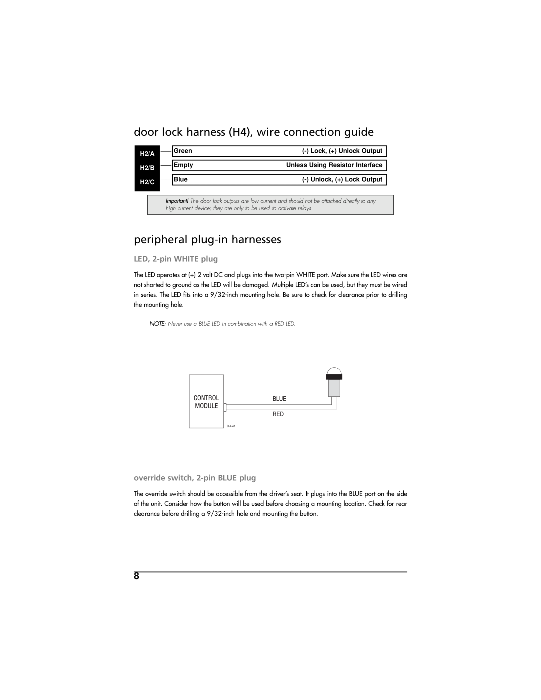
LED, 2-pin WHITE plug
door lock harness H4, wire connection guide
override switch, 2-pin BLUE plug
peripheral plug-in harnesses
Pro Security Programmer interface, 3-pin port
module programming
To enter the learn routine
More than 15 seconds elapses between programming steps
4. Release. The Override switch can now be released
The Override switch is pressed too many times
The learn routine will be exited if The ignition is turned on
feature descriptions
system features menus
remote coding
Function
standard configuration
remote configurations
single button arm/disarm configuration
power-up
Pro Security Programmer Override Switch 3-Pin 2-Wire Door
wiring quick reference guide
Lock Harness
2003 Directed Electronics, Inc. - All rights reserved GK10
Ungo Pro Security 661 W. Redondo Beach Blvd Gardena, Ca
800-GO-CLARION
Get Started Get Protected
Top
Page
Image
Contents