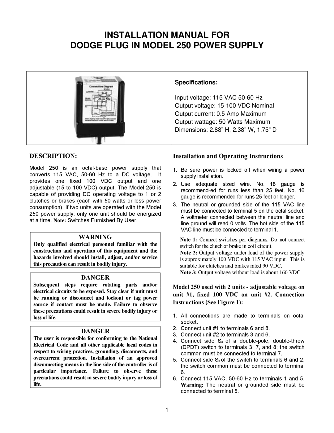
INSTALLATION MANUAL FOR
DODGE PLUG IN MODEL 250 POWER SUPPLY
Specifications:
Input voltage: 115 VAC
Output voltage:
Output current: 0.5 Amp Maximum
Output wattage: 50 Watts Maximum
Dimensions: 2.88” H, 2.38” W, 1.75” D
DESCRIPTION:
Model 250 is an
Installation and Operating Instructions
1.Be sure power is locked off when wiring a power supply installation.
2.Use adequate sized wire. No. 18 gauge is
3.The neutral or grounded side of the 115 VAC line must be connected to terminal 5 on the octal socket. A voltmeter connected between the neutral line and line ground will read 0 volts. The hot side of the 115 VAC line must be connected to terminal 1.
WARNING
Only qualified electrical personnel familiar with the construction and operation of this equipment and the hazards involved should install, adjust, and/or service this precaution can result in bodily injury.
DANGER
Subsequent steps require rotating parts and/or electrical circuits to be exposed. Stay clear if unit must be running or disconnect and lockout or tag power source if contact must be made. Failure to observe these precautions could result in severe bodily injury or loss of life.
DANGER
The user is responsible for conforming to the National Electrical Code and all other applicable local codes in respect to wiring practices, grounding, disconnects, and overcurrent protection. Installation of an approved disconnecting means in the line side of the controller is of particular importance. Failure to observe these precautions could result in severe bodily injury or loss of life.
Note 1: Connect switches per diagrams. Do not connect switch for the clutch or brake in coil circuit.
Note 2: Output voltage under load of the power supply is approximately 100 VDC with 115 VAC input. This is suitable for clutches and brakes rated 90 VDC.
Note 3: Output voltage without load is about 160 VDC.
Model 250 used with 2 units - adjustable voltage on unit #1, fixed 100 VDC on unit #2. Connection Instructions (See Figure 1):
1.All connections are made to terminals on octal socket.
2.Connect unit #1 to terminals 6 and 8.
3.Connect unit #2 to terminals 3 and 6.
4.Connect side Sa of a
5.Connect side Sb of the switch to terminals 6 and 2; the switch common must be connected to terminal 6.
6.Connect 115 VAC,
1
