Interchassis Management Bus (ICMB) Board
Removing the ICMB Board
See Figure 35.
1.Observe the safety precautions, warnings, and cautions at the beginning of this chapter.
2.Remove the top and 240 VA protective covers (see “Removing the Top Cover” on page 98).
3.Disconnect the ICMB signal cable from its connector on the I/O riser board.
4.Remove and save the screw that attaches the ICMB board to the I/O tray.
5.Push on the tabs of the
6.Place the board on a nonconductive,
Installing the ICMB Board
See Figure 35.
1.Remove the ICMB board from its protective wrapper.
2.Position the board over the
3.Press the board onto the
4.Make sure the board is properly aligned, then tighten the screw firmly (8.0
5.Connect the signal cable to its connector on the I/O riser board.
6.Reinstall the top and 240 VA protective covers (see “Installing the Top Cover” on page 99).
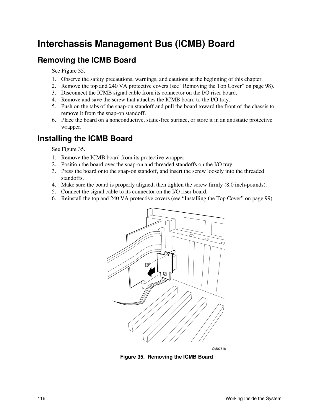
OM07518
Figure 35. Removing the ICMB Board
116 | Working Inside the System |