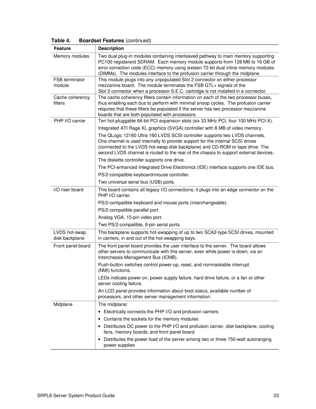
Table 4. Boardset Features (continued)
Feature
Memory modules
FSB terminator module
Cache coherency filters
PHP I/O carrier
I/O riser board
LVDS
Front panel board
Midplane
Description
Two dual
This module plugs into any unpopulated Slot 2 connector on either processor mezzanine board. The module terminates the FSB GTL+ signals of the
Slot 2 connector when a processor S.E.C. cartridge is not installed in a connector.
The cache coherency filters contain information on each of the two processor buses, thus enabling each bus to perform with minimal snoop cycles. The profusion carrier requires that these filters be populated if the server has two processor mezzanine boards that are both populated with processors.
Ten
Integrated ATI Rage XL graphics (SVGA) controller with 8 MB of video memory.
The QLogic 12160 Ultra 160 LVDS SCSI controller supports two LVDS channels. One channel is used internally to provide support for the internal SCSI drives (connected to the LVDS
The diskette controller supports one drive.
The
Two universal serial bus (USB) ports.
This board contains all legacy I/O connections; it plugs into an edge connector on the PHP I/O carrier.
Analog VGA,
Two
This backplane supports
The front panel board provides the user interface to the server. The board allows other servers to communicate with this server, even while power is down, via an Interchassis Management Bus (ICMB).
LEDs indicate power on, power supply failure, hard drive failure, or a fan or other server cooling failure.
An LCD panel provides information about boot status, available number of processors, and other server management information.
The midplane:
∙Electrically connects the PHP I/O and profusion carriers
∙Contains the sockets for the memory modules
∙Distributes DC power to the PHP I/O and profusion carrier, disk backplane, cooling fans, memory boards, and front panel board
∙Distributes the power load of the server among two or three
SRPL8 Server System Product Guide | 23 |