PCI Configuration and Device Map
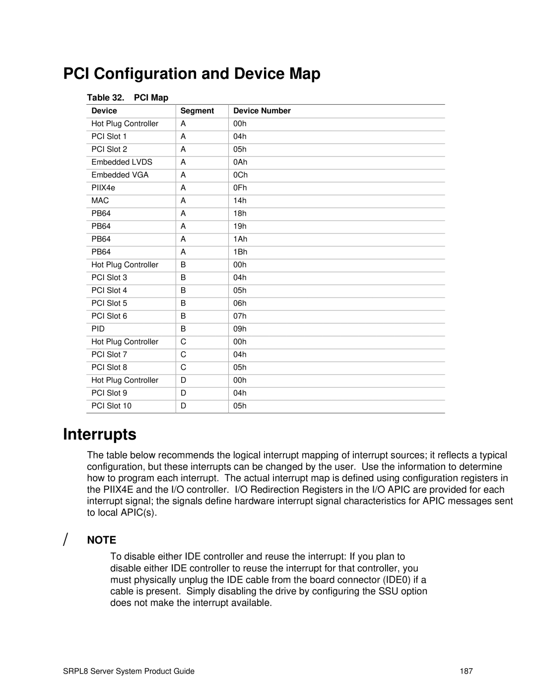
Table 32. PCI Map
Device
Hot Plug Controller
PCI Slot 1
PCI Slot 2
Embedded LVDS
Embedded VGA
PIIX4e
MAC
PB64
PB64
PB64
PB64
Hot Plug Controller
PCI Slot 3
PCI Slot 4
PCI Slot 5
PCI Slot 6
PID
Hot Plug Controller
PCI Slot 7
PCI Slot 8
Hot Plug Controller
PCI Slot 9
PCI Slot 10
Segment
A
A
A
A
A
A
A
A
A
A
A
B
B
B
B
B
B
C
C
C
D
D
D
Device Number
00h
04h
05h
0Ah
0Ch
0Fh
14h
18h
19h
1Ah
1Bh
00h
04h
05h
06h
07h
09h
00h
04h
05h
00h
04h
05h
Interrupts
The table below recommends the logical interrupt mapping of interrupt sources; it reflects a typical configuration, but these interrupts can be changed by the user. Use the information to determine how to program each interrupt. The actual interrupt map is defined using configuration registers in the PIIX4E and the I/O controller. I/O Redirection Registers in the I/O APIC are provided for each interrupt signal; the signals define hardware interrupt signal characteristics for APIC messages sent to local APIC(s).
✏NOTE
To disable either IDE controller and reuse the interrupt: If you plan to disable either IDE controller to reuse the interrupt for that controller, you must physically unplug the IDE cable from the board connector (IDE0) if a cable is present. Simply disabling the drive by configuring the SSU option does not make the interrupt available.
SRPL8 Server System Product Guide | 187 |