Chassis Back Controls and Features
A | B C D |
| E |
| F |
N | G |
| |
| H |
| I |
M | J |
L |
|
K |
|
| OM08781 |
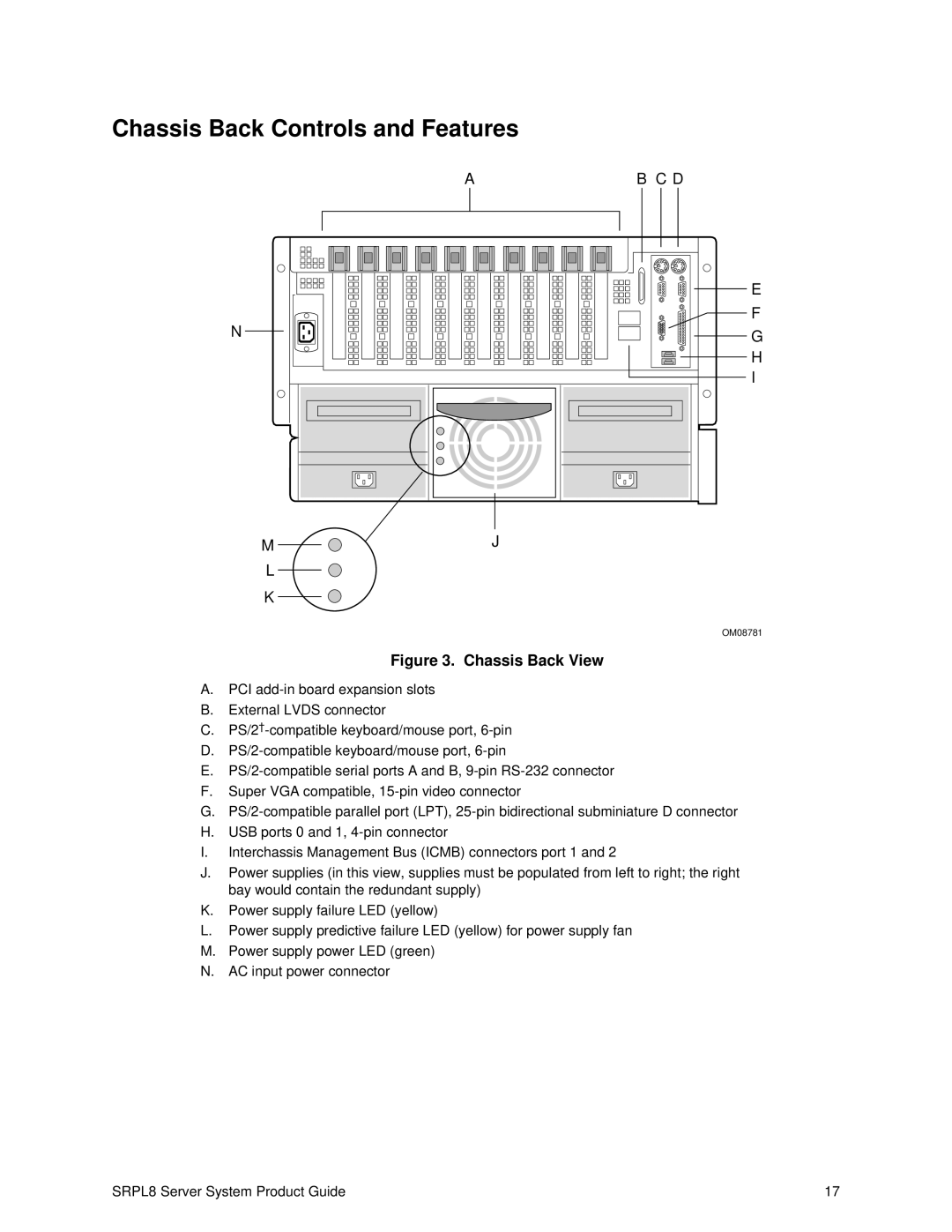
Figure 3. Chassis Back View
A.PCI
B.External LVDS connector
C.
D.
E.
F.Super VGA compatible,
G.
H.USB ports 0 and 1,
I.Interchassis Management Bus (ICMB) connectors port 1 and 2
J.Power supplies (in this view, supplies must be populated from left to right; the right bay would contain the redundant supply)
K.Power supply failure LED (yellow)
L.Power supply predictive failure LED (yellow) for power supply fan
M.Power supply power LED (green)
N.AC input power connector
SRPL8 Server System Product Guide | 17 |