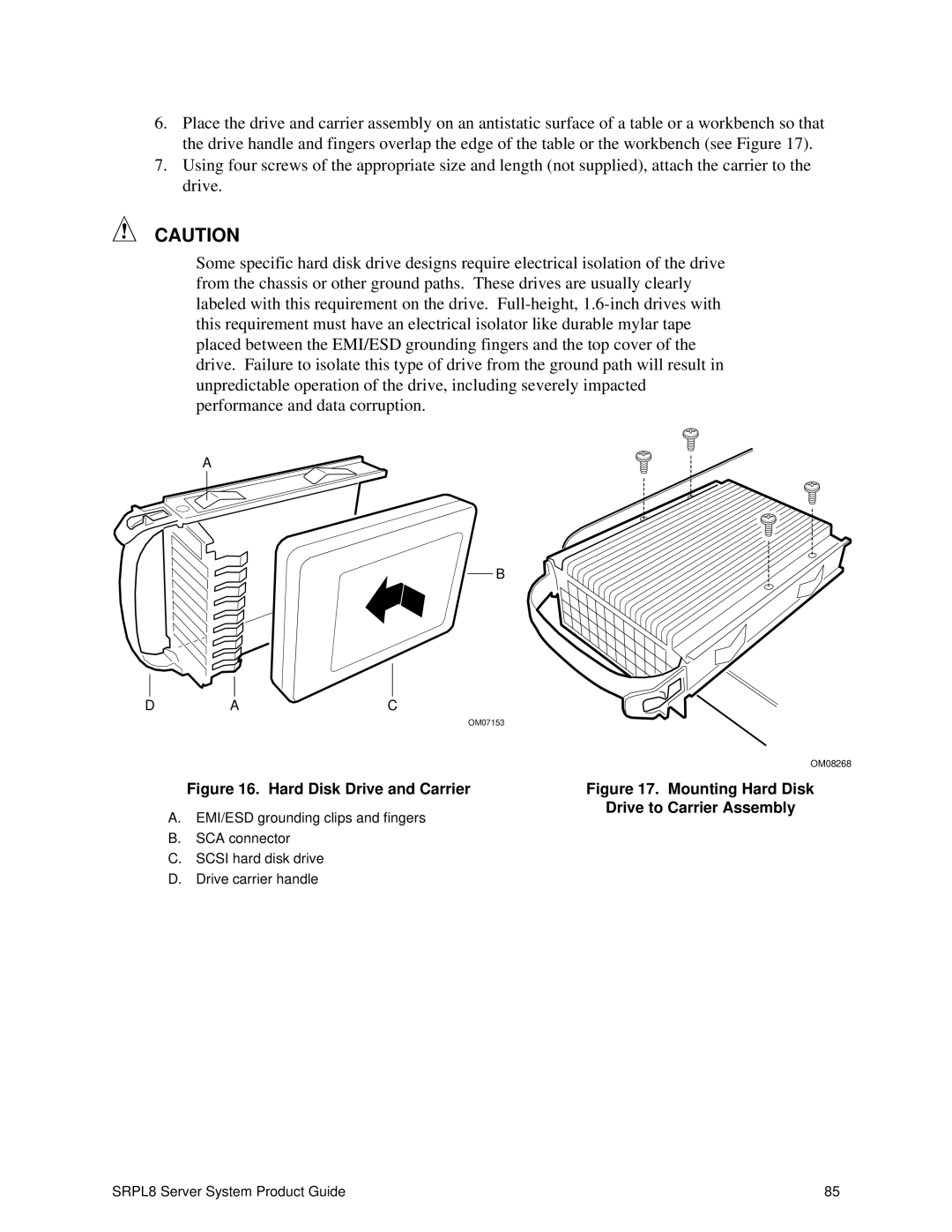
6.Place the drive and carrier assembly on an antistatic surface of a table or a workbench so that the drive handle and fingers overlap the edge of the table or the workbench (see Figure 17).
7.Using four screws of the appropriate size and length (not supplied), attach the carrier to the drive.
CAUTION
Some specific hard disk drive designs require electrical isolation of the drive from the chassis or other ground paths. These drives are usually clearly labeled with this requirement on the drive.
A
B
D | A | C |
|
|
| OM07153 |
|
|
|
| OM08268 |
| Figure 16. Hard Disk Drive and Carrier | Figure 17. Mounting Hard Disk | |
A. EMI/ESD grounding clips and fingers | Drive to Carrier Assembly | ||
| |||
B. | SCA connector |
|
|
C. SCSI hard disk drive |
|
| |
D. | Drive carrier handle |
|
|
SRPL8 Server System Product Guide | 85 |