A
B CD E
OM10708
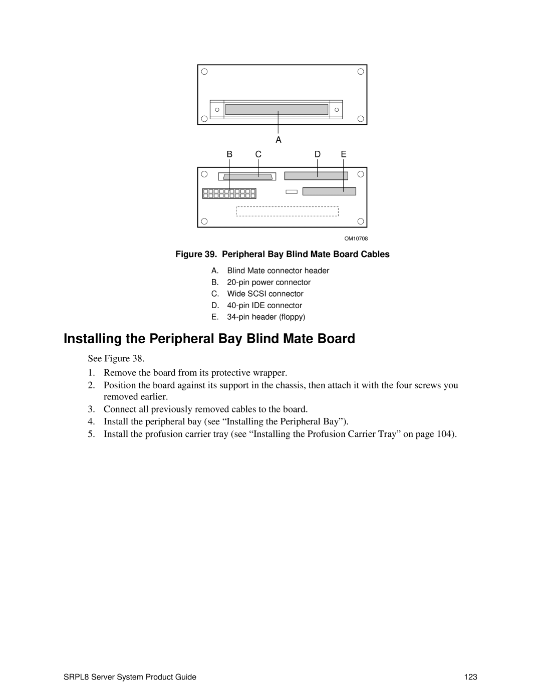
Figure 39. Peripheral Bay Blind Mate Board Cables
A.Blind Mate connector header
B.
C.Wide SCSI connector
D.
E.
Installing the Peripheral Bay Blind Mate Board
See Figure 38.
1.Remove the board from its protective wrapper.
2.Position the board against its support in the chassis, then attach it with the four screws you removed earlier.
3.Connect all previously removed cables to the board.
4.Install the peripheral bay (see “ Installing the Peripheral Bay” ).
5.Install the profusion carrier tray (see “Installing the Profusion Carrier Tray” on page 104).
SRPL8 Server System Product Guide | 123 |