Configuration Switches
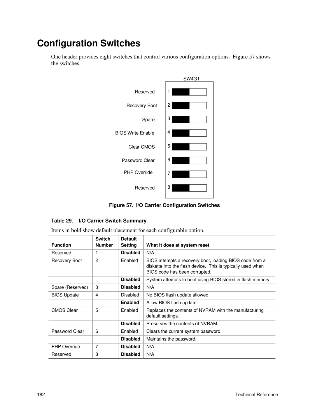
One header provides eight switches that control various configuration options. Figure 57 shows the switches.
Reserved
Recovery Boot
Spare
BIOS Write Enable
Clear CMOS
Password Clear
PHP Override
Reserved
SW4G1
1
2 ![]()
![]()
3 ![]()
![]()
4 ![]()
![]()
5 ![]()
![]()
6 ![]()
![]()
7 ![]()
![]()
8 ![]()
![]()
Figure 57. I/O Carrier Configuration Switches
Table 29. I/O Carrier Switch Summary
Items in bold show default placement for each configurable option.
| Switch |
Function | Number |
Reserved | 1 |
Recovery Boot | 2 |
|
|
|
|
Spare (Reserved) | 3 |
BIOS Update | 4 |
|
|
CMOS Clear | 5 |
|
|
|
|
Password Clear | 6 |
|
|
PHP Override | 7 |
Reserved | 8 |
Default Setting
Disabled
Enabled
Disabled
Disabled
Disabled
Enabled
Enabled
Disabled
Enabled
Disabled
Disabled
Disabled
What it does at system reset
N/A
BIOS attempts a recovery boot, loading BIOS code from a diskette into the flash device. This is typically used when BIOS code has been corrupted.
System attempts to boot using BIOS stored in flash memory.
N/A
No BIOS flash update allowed.
Allow BIOS flash update.
Replaces the contents of NVRAM with the manufacturing default settings.
Preserves the contents of NVRAM.
Clears the current system password.
Maintains the password.
N/A
N/A
182 | Technical Reference |