Removing a Processor
See Figure 51 (page 148) and Figure 52 (page 149).
1.Observe the safety and ESD precautions at the beginning of this chapter.
2.Remove the top cover (see “Removing the Top Cover” on page 98).
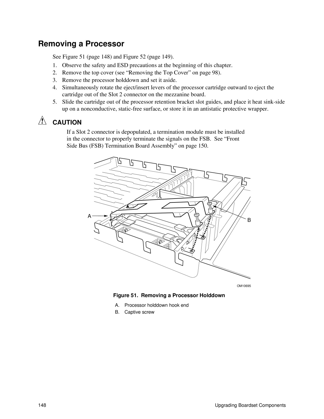
3.Remove the processor holddown and set it aside.
4.Simultaneously rotate the eject/insert levers of the processor cartridge outward to eject the cartridge out of the Slot 2 connector on the mezzanine board.
5.Slide the cartridge out of the processor retention bracket slot guides, and place it heat
CAUTION
If a Slot 2 connector is depopulated, a termination module must be installed in the connector to properly terminate the signals on the FSB. See “ Front Side Bus (FSB) Termination Board Assembly” on page 150.
A ![]()
![]()
![]()
B
OM10695
Figure 51. Removing a Processor Holddown
A.Processor holddown hook end
B.Captive screw
148 | Upgrading Boardset Components |