C
D
A
B
OM08752
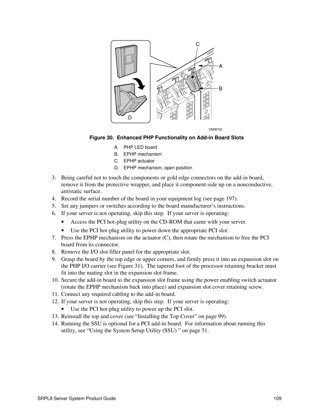
Figure 30. Enhanced PHP Functionality on Add-in Board Slots
A.PHP LED board
B.EPHP mechanism
C.EPHP actuator
D.EPHP mechanism, open position
3.Being careful not to touch the components or gold edge connectors on the
4.Record the serial number of the board in your equipment log (see page 197).
5.Set any jumpers or switches according to the board manufacturer’s instructions.
6.If your server is not operating, skip this step. If your server is operating:
∙Access the PCI
∙Use the PCI
7.Press the EPHP mechanism on the actuator (C), then rotate the mechanism to free the PCI board from its connector.
8.Remove the I/O slot filler panel for the appropriate slot.
9.Grasp the board by the top edge or upper corners, and firmly press it into an expansion slot on the PHP I/O carrier (see Figure 31). The tapered foot of the processor retaining bracket must fit into the mating slot in the expansion slot frame.
10.Secure the
11.Connect any required cabling to the
12.If your server is not operating, skip this step. If your server is operating:
∙Use the PCI
13.Reinstall the top and cover (see “Installing the Top Cover” on page 99).
14.Running the SSU is optional for a PCI
SRPL8 Server System Product Guide | 109 |