6.Install the LCD module (see “LCD Module” on page 102).
7.Install the insulating material removed earlier from the front panel board.
8.Install the fan array housing (see “Fan Array Housing” on page 101).
9.Install the top cover (see “Installing the Top Cover” on page 99).
| A |
|
= D | B | C |
= E |
|
|
OM07322
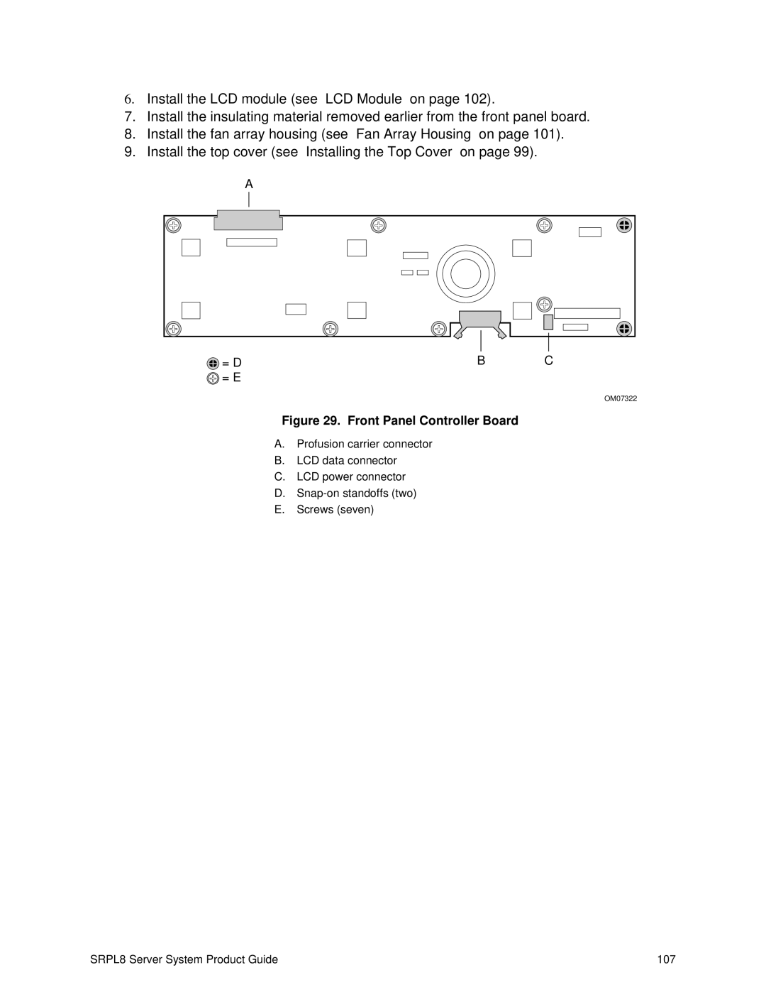
Figure 29. Front Panel Controller Board
A.Profusion carrier connector
B.LCD data connector
C.LCD power connector
D.
E.Screws (seven)
SRPL8 Server System Product Guide | 107 |