B
A ![]()
A ![]()
![]()
![]()
![]() A
A
OM10692
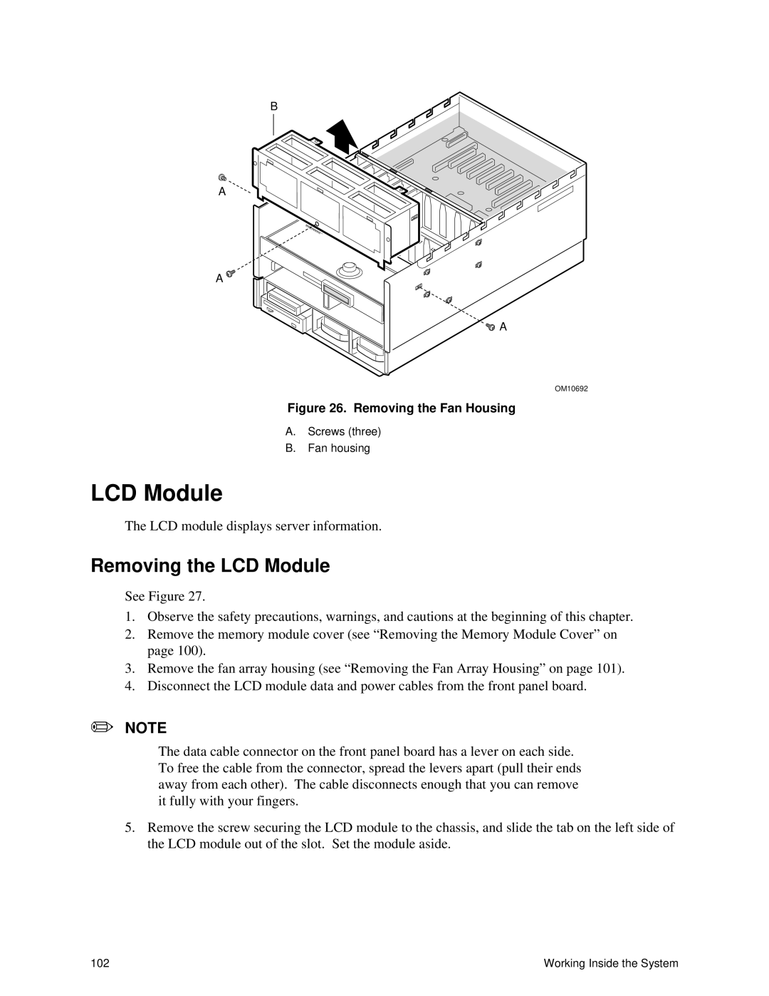
Figure 26. Removing the Fan Housing
A.Screws (three)
B.Fan housing
LCD Module
The LCD module displays server information.
Removing the LCD Module
See Figure 27.
1.Observe the safety precautions, warnings, and cautions at the beginning of this chapter.
2.Remove the memory module cover (see “Removing the Memory Module Cover” on page 100).
3.Remove the fan array housing (see “Removing the Fan Array Housing” on page 101).
4.Disconnect the LCD module data and power cables from the front panel board.
✏NOTE
The data cable connector on the front panel board has a lever on each side. To free the cable from the connector, spread the levers apart (pull their ends away from each other). The cable disconnects enough that you can remove it fully with your fingers.
5.Remove the screw securing the LCD module to the chassis, and slide the tab on the left side of the LCD module out of the slot. Set the module aside.
102 | Working Inside the System |